3 crs-500 power connections – Comtech EF Data CRS-500 User Manual
Page 98

CRS-500 1:N Redundancy System
Revision 2
Cables and Connections
MN-CRS500
4–42
4.5.3 CRS-500 Power Connections
Connect the power cords as follows:
Step
Task
1
Ensure that both power supply switches are in the OFF position before connecting the power
supply power cords.
2
Connect the female end of each supplied power cord into its power input (one to each power
input module).
3
Plug the male end of each power cord into its power source. It is recommended that each
power cord is connected to an alternate power source.
Note: The auto-sensing power supplies do not require any adjustments.
4
Do not turn the CRS-500 power switches ON until instructed in Sect.4.5.4.
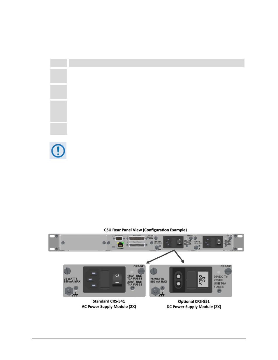
1. As shown in Figure 4-17, each CRS-500 is shipped with two power supply
modules installed in the rear panel of the CSU – the IEC line input connector for
each power supply module contains the ON/OFF switch for that module. It is
recommended that both power supplies, connected to individual power
sources, are used for maximum reliability.
2. Each power supply module contains two fuses, one each for line and neutral
connections (or L1, L2 where appropriate). These are seated in a fuse holder
that is press-fit into the body of the module.
3. For continued operator safety, always replace the fuses with the correct type
and rating. For 115/230 volt AC operation, use T1A (slow-blow) 20 mm fuses.
Figure 4-17. CRS-500 Power Connections (CSU Rear Panel)
