3 led indicators, 1 /switch status led indicators, 1 switch status led indicators – Comtech EF Data CRS-500 User Manual
Page 120
CRS-500 1:N Redundancy System
Revision 2
CSU Front Panel Operation
MN-CRS500
7–4
7.1.3 LED Indicators
Depending on the user application, most of the LED indicators are available
remotely via SNMP (Simple Network Management Protocol).
“crs500SlotStatusTable” contains the Unit/Tx/Rx status indicator array. See Sect.
8.3 SNMP Interface for information about using this Ethernet-based remote
product management protocol.
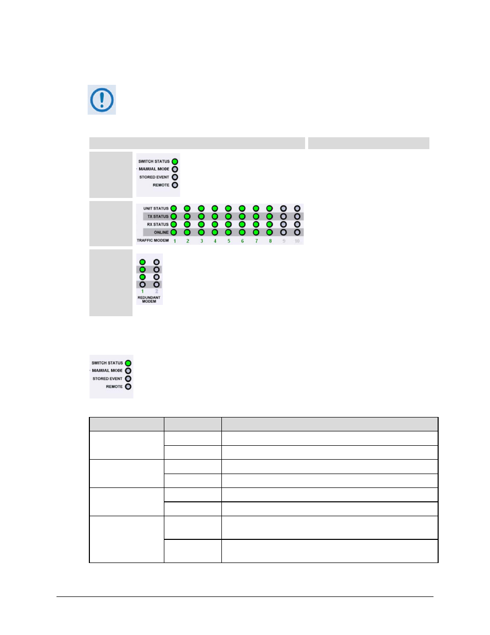
LED Indicator Feature
Description
Switch
Status
Four LEDs show the operating state of
the CRS-500 System..
Traffic
Modem
Status
10 sets of four LEDs + the active Traffic
Modem number show the operating
state of up to 10 Traffic modems.
Redundant
Modem
Status
Two sets of four LEDs + the active
Redundant Modem number show the
operating state of the Redundant
Modem.
(Note: Only RM 1 is operational. RM 2
is reserved for future 2:N functionality.)
7.1.3.1 Switch Status LED Indicators
Table 7-1 describes the behavior of the four front panel LEDs adjacent to the
keypad, which indicate operational status of the CRS-500 CSU:
Table 7-1. Switch Status LED Indicators Group
LED
Color
Condition
SWITCH STATUS
Green
Normal operation (no Switch Faults)
Red
Switch Fault, e.g., PSU fault or COMMS failure
MANUAL MODE
Off
Switch is in Auto Mode
Green
CAUTION: Switch is in Manual mode
STORED EVENT
Off
No Stored Events
Green
Switch has Stored Events
REMOTE
Off
Switch in Local Mode – remote monitoring is possible; remote
configuration control is not allowed
Orange
Switch in Remote Mode – configuration changes are disabled via the
front panel keypad