2 data switch unit (dsu), 1 dsu front panel – Comtech EF Data CRS-500 User Manual
Page 35
CRS-500 1:N Redundancy System
Revision 2
Introduction
MN-CRS500
1–9
1.3.2 Data Switch Unit (DSU)
The front panel of the Data Switch Unit (DSU) can contain a maximum of 10 Traffic Modem
Interfaces (TMIs) and one Redundant Modem Interface (RMI). Two connectors on the rear panel
of the DSU are provided for connection of the DSU to the CRS-500’s CSU and optional ISUs.
The traffic data from the user interface to the Traffic Modem interface passes through
normally-closed relay contacts on the TMI card. In the event that both power supplies are lost,
or if a traffic-carrying TMI and its cables are removed, no interruption of traffic data occurs.
When using the KT-0000072 DSU Rack Mounting Kit, the DSU may be installed into the rear or
on top of the rack in any of two horizontal or two vertical positions. This allows the unit to be
positioned or hinged outward to permit convenient access to the RMI/TMIs for cable
connections between the DSU, CSU, ISUs, and the modems. See Chapter 3. INSTALLATION for
details.
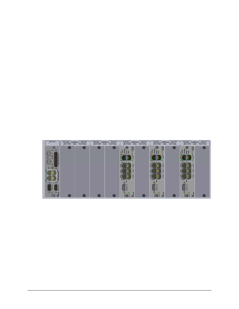
1.3.2.1 DSU Front Panel
An example of a DSU front panel configured for 1:3 redundancy for the CDM-625 is shown in
Figure 1-11. CRS-500 DSU Front View – CDM-625 1:3 Configuration Example