2 initial start-up – Comtech EF Data CRS-500 User Manual
Page 48
CRS-500 1:N Redundancy System
Revision 2
Initial Start-up and Configuration Check Lists
MN-CRS500
2–2
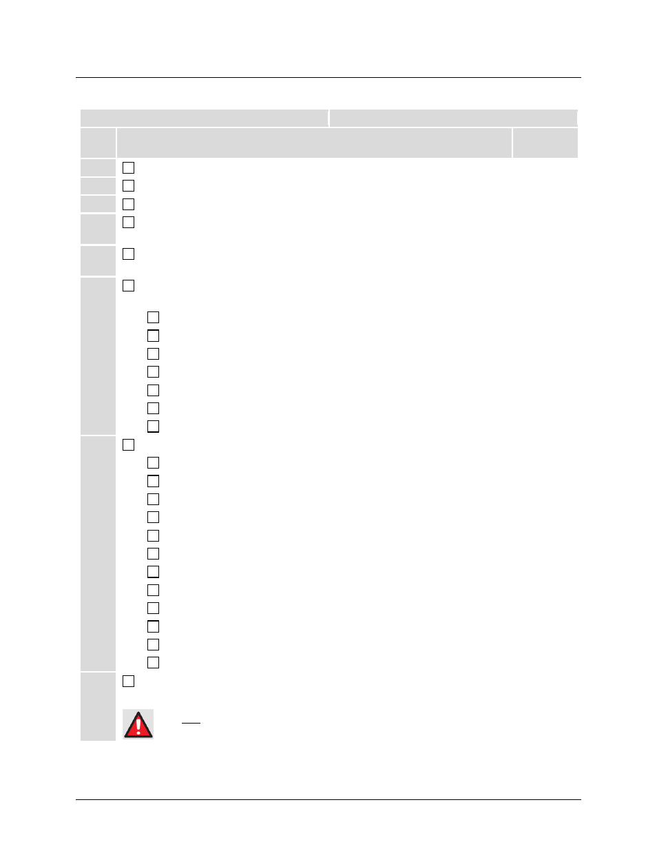
2.2 Initial Start-up
* User-provided equipment
** Purchased Separately
Step Procedure
Chapter
Reference
1
Unpack and inspect the CRS-500 components.
3
2
Install the CRS-500 components and modems** in a rack.
3
3
Connect cables between the CRS-500 Switch components (CSU, DSU, ISU).
4
4
Connect cables to/from the modems** and the CRS-500 components.
4
5
Connect IF cables* between either the CRS-500 ISU(s) or the signal splitters, and
the IF Downconverter*.
4
6
Configure modems for use in the CRS-500 1:N Redundancy system. Typical for all
modems:
6
Power on the modems.
5
Verify that modems are running the modem’s most recent firmware version.
6
Enable Redundancy Mode.
6
Set IP Address (for M&C to/from the CRS-500).
6
Set Redundancy Traffic IP Address (if applicable).
6
Select Dedicated Ethernet Port (if applicable).
6
Configure PMSI (if Carrier-in-Carrier [CnC] is used).
6
7
Configure the CRS-500 CSU for 1:N Operation:
Power on the CRS-500.
5
Verify that the CRS-500 CSU is running its most current firmware version.
5
Configure the CRS-500’s “Switch Management” IP address.
7
Set Operating mode to Manual Switching mode.
7
Set IP address (for M&C to/from modems)
7
Set Redundancy Mode to 1:N.
7
Activate Traffic Modem(s).
7
Select Traffic Modem(s) to Bridge.
7
Set Holdoff (Backup and Restore) times.
7
Select Alarm Masks for Switch and/or Modems.
Perform Redundancy System Checkout.
6
Set Operating Mode to Auto Switching Mode.
7
8
Connect RF cables* between the RF Upconverters* and either the CRS-500 ISU(s)
or the signal combiners.
4
DO NOT CONNECT the IF to any Upconverters UNTIL AFTER the CRS-500 1:N Redundancy System
is fully cabled and configured. Do this to prevent unintended signals from reaching the satellite.