Comtech EF Data CRS-500 User Manual
Page 102
CRS-500 1:N Redundancy System
Revision 2
Updating Firmware
MN-CRS500
5–2
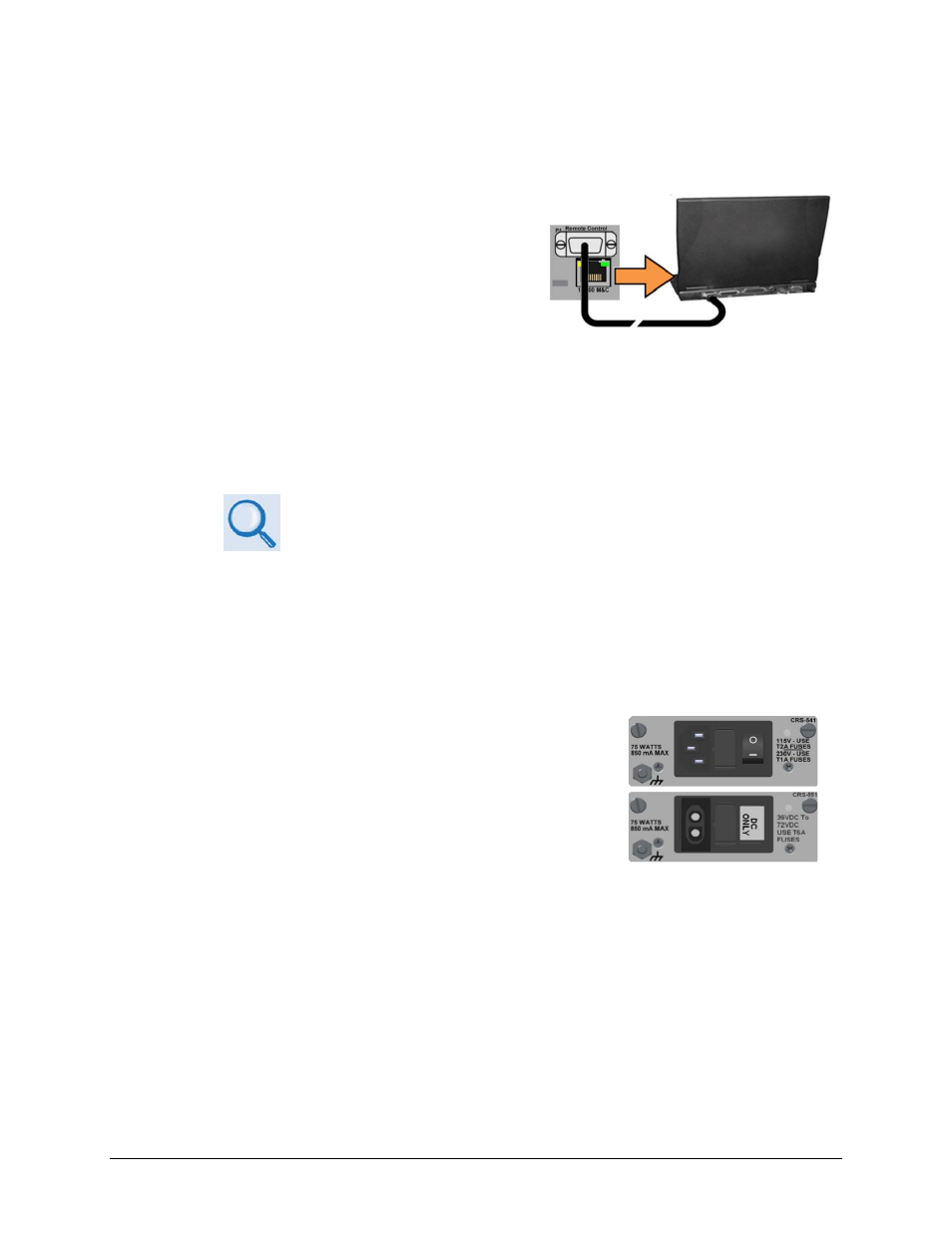
(Top) Standard CRS-541 AC Module
(Bottom) Optional CRS-551 DC Module
• A CAT5 Ethernet cable to connect a user PC Ethernet port to the CRS-500 (for use of the
Ethernet-based remote product management interface).
A. Connect the 9-pin serial cable from the
CSU’s CRS-530 System Controller Module
‘P1 | Remote Control’ port to a serial port
on the user PC.
B. Connect the CAT5 Ethernet cable from the CRS-500 system to an Ethernet port on the
user PC via a hub or a switch, or direct connection. Note that the location for this M&C
connection depends both on the deployed modem model and the mode of Ethernet in
use. See Chapter 4. CABLES AND CONNECTIONS for details.
C. On the PC: Open the terminal emulator program.
Refer to your terminal emulator program HELP feature or user guide for
operating and configuration instructions.
Configure the utility program serial port communication and terminal display operation:
• 38400 bps (Baud Rate)
• 8 Data Bits
• 1 Stop Bit
• Parity = NO
• Port Flow Control = NONE
• Display New line Rx/Tx: CR
• Local Echo = ON
D. Apply power to the CRS-500 (at the CSU rear panel):
E. On the PC: Query the CRS-500 system and firmware information in one of the
following ways:
• Via the front panel display – See the top-level screen (press the [CLEAR] key several
times to view) for the firmware version. The firmware number can be found within
the SELECT: UTIL Firmware Info Boot, Bulk1, or Bulk2 submenus.