Comtech EF Data CRS-500 User Manual
Page 49
CRS-500 1:N Redundancy System
Revision 2
Initial Start-up and Configuration Check Lists
MN-CRS500
2–3
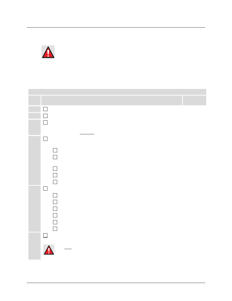
2.3 Adding or Removing a Traffic Modem to/from an Operating
CRS-500 1:N Redundancy System
If adding a Traffic Modem to or removing a Traffic Modem from an operating
CRS-500 1:N Redundancy System, take care not to interfere with the existing
traffic. Make sure to correctly perform the cabling and power-up or power-down
sequences. Do not allow the modem Tx carrier to cause contention in the system.
2.3.1
Adding a Traffic Modem to an Operating C R S -500 1:N
R edundancy S ys tem
* User-provided equipment
Step
Procedure
Chapter
Reference
1
Unpack and inspect the modem.
3
2
Install the modem into the rack* at its desired location.
3
3
Connect cables between the powered OFF modem and the CRS-500 1:N
Redundancy System components (CRS-500 CSU/DSU/ ISU(s), existing modems)
and equipment * (excluding the Upconverter *).
4
4
Configure the modem for use in the CRS-500 1:N Redundancy System. Typical for
each added modem:
6
Power ON the modem.
5
Verify that the modem is running its most recent firmware version, and that all
other modems in the system are running this same firmware version.
5
Enable Redundancy Mode.
6
Set IP Address (for M&C to/from the CRS-500).
6
Configure PMSI (if Carrier-in-Carrier [CnC] is used).
6
5
Configure the CRS-500 CSU for 1:N Operation with the new modem:
7
Set Operating mode to Manual Switching mode.
7
Set IP address (for M&C to/from modems)
7
Set Redundancy Traffic IP address (if applicable)
7
Activate the new Traffic Modem.
7
Perform Redundancy System Checkout.
2
Set Operating Mode to Auto Switching Mode.
7
6
Connect RF* cables between either the CRS-500 ISU(s) or the signal combiners,
and the RF Upconverters *.
4
DO NOT CONNECT the IF to any Upconverters UNTIL AFTER the CRS-500 1:N Redundancy
System is fully cabled and configured. Do this to prevent unintended signals from reaching the
satellite.