2 config | modem – Comtech EF Data CRS-500 User Manual
Page 151
CRS-500 1:N Redundancy System
Revision 2
Ethernet-Based Remote Product Management
MN-CRS500
8–13
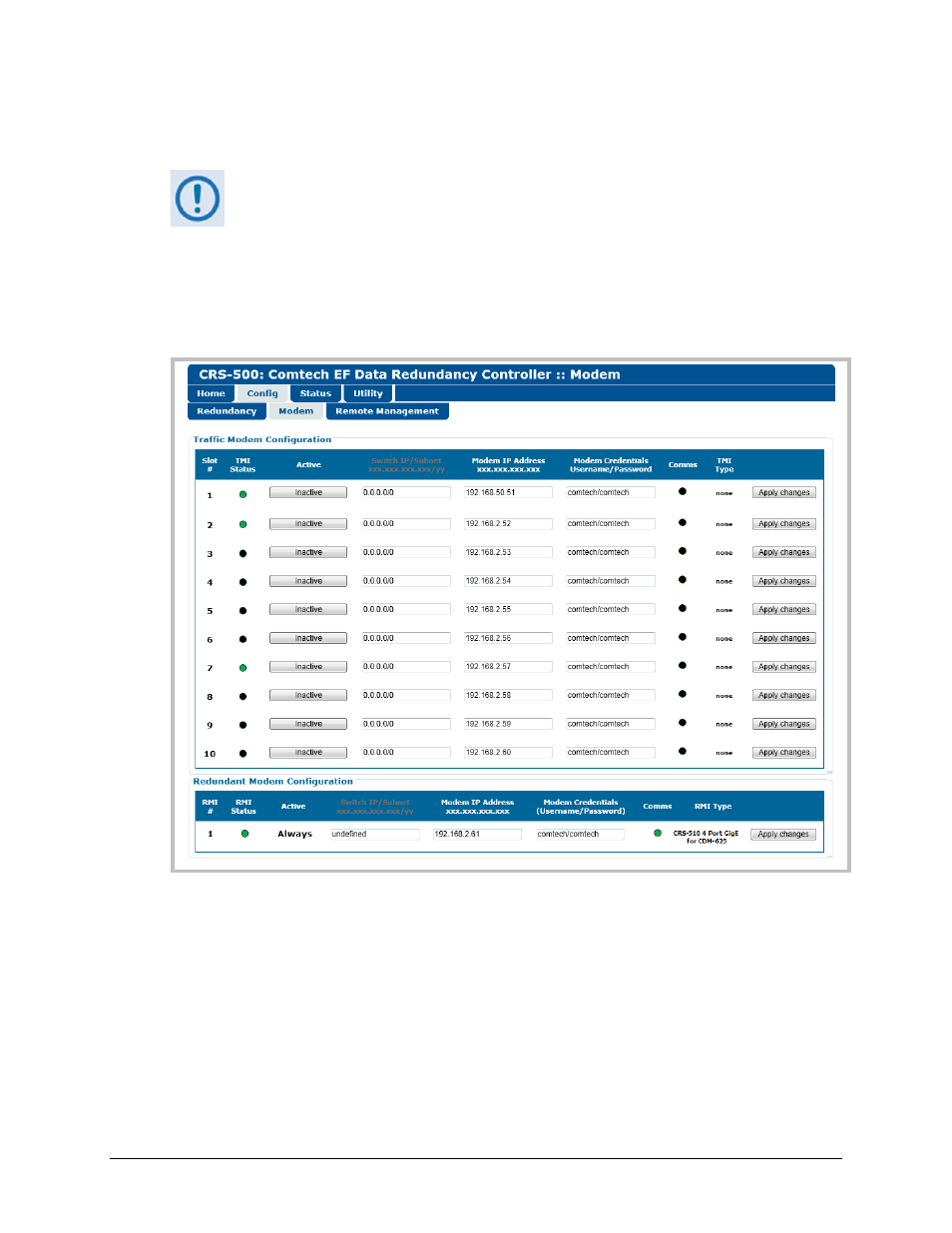
8.5.3.2.2 Config | Modem
The appearance of this page is driven by the default 1:N Capacity (2:N is reserved
for future functionality), as designated in the Redundancy Configuration section of
the Config | Redundancy page.
This page provides a heads-up display for the configuration of the CRS-500 Data Switch Unit
(DSU). Use this page to configure or monitor the IP communications of, and to obtain
operational status information on, the Traffic Modem Interfaces (TMIs) and Redundant Modem
Interfaces (RMIs) that comprise the CRS-500 1:N Redundancy System.
Figure 8-3. Config | Modem Page
See Table 8-1 for a summary of the Traffic and Redundant Modem Configuration sections
functionality. The ‘Chapter’ column directs you to the manual chapter that provides detail about
a specific feature.
Traffic Modem or Redundant Modem Configuration
To configure or edit a Traffic or Redundant Modem IP Address – Type in the IP Address of the
modem that is assigned to that specific Slot #, and then click [Apply Changes].