Comtech EF Data CRS-500 User Manual
Page 51
CRS-500 1:N Redundancy System
Revision 2
Initial Start-up and Configuration Check Lists
MN-CRS500
2–5
2.4 Using the CSU Front Panel to Verify System Operation
Once the connected modems and CRS-500 have been properly configured, make sure the
CRS-500 is operating fault-free. Make sure that the modems’ “Online” and “Bridge” functions
and status are operating as intended.
1. Complete all modem and switch installation and configuration tasks before
proceeding.
2. Refer to the pertinent modem’s Installation and Operation Manual for
detailed operational information
Via the CSU’s front panel operations (i.e., M&C accomplished by observing the LED Indicator
activity and Video Fluorescent Display (VFD) messages, and subsequent operations using the
keypad), use the following check list to verify proper CRS-500 1:N Redundancy System
operation:
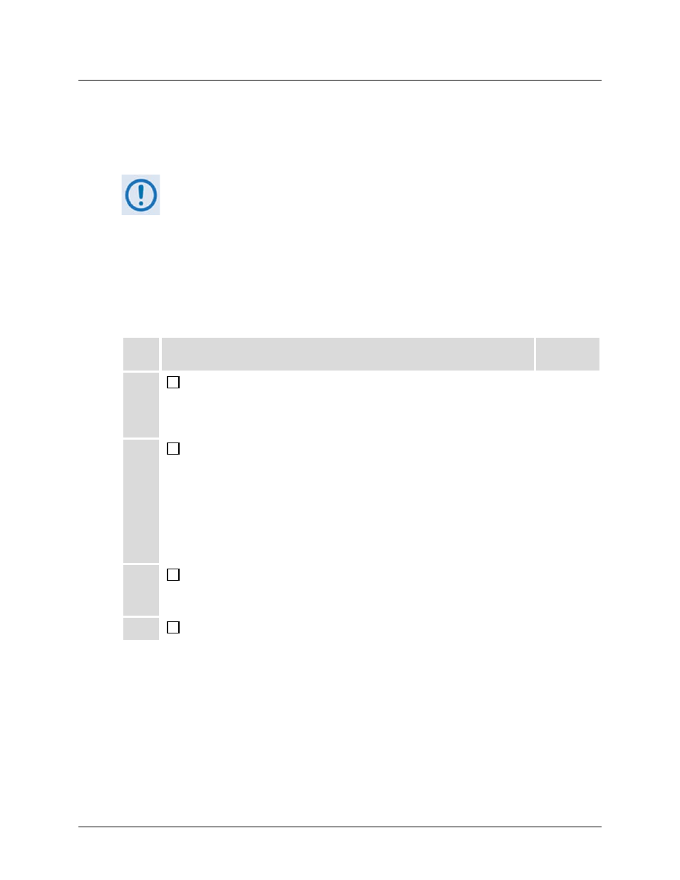
Step Procedure
Chapter
Reference
1
Verify that the Switch “UNIT STATUS” LED is green, indicating that there
are no faults. If this LED is red, go to either the MONITOR ALARMS
submenu (via the CSU front panel) or view the scrollable event log on the
Web Server Interface’s MONITOR | STATUS page to investigate further.
7 or 8
2
Verify that the “UNIT STATUS”, “TX STATUS”, and “RX STATUS” LEDs for
each active modem are green, indicating that there are no faults. If any
LEDs are red, go to either the MONITOR ALARMS submenu (via the
Modem front panel) or view the scroll able event log on the Web Server
Interface’s MONITOR | STATUS page to investigate further.
Note that the LEDs on each modem front panel correspond similarly to the
LEDs provided on the CSU front panel. Faults and events may also be
reviewed using the front panel of the faulted modem..
7 or 8
3
Verify that the “ONLINE” LED is lit green for all active Traffic Modems.
Traffic Modems that are being bridged will blink in sync with its
corresponding Redundant Modem.
7
4
Verify that the “ONLINE” LED is not lit for the Redundant Modem(s).
7