3 crs-500 standard and optional components, 1 control switch unit (csu) – Comtech EF Data CRS-500 User Manual
Page 31
CRS-500 1:N Redundancy System
Revision 2
Introduction
MN-CRS500
1–5
1.3 CRS-500 Standard and Optional Components
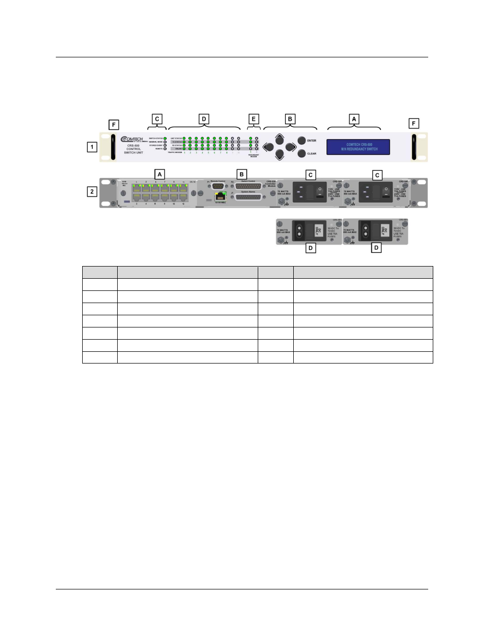
1.3.1 Control Switch Unit (CSU)
Feature Description
Feature Description
1
CSU Front Panel View
2
CSU Rear Panel View
A
Video Fluorescent Display (VFD)
A
CRS-512 Ethernet M&C Interface
B
6-Button Keypad
B
CRS-530 System Controller Module
C
Switch Status LED Group
C
Standard CRS-541 AC Power Supply
D
Traffic Modem Status LED Group
D
Optional CRS-551 DC Power Supply
E
Redundant Modem Status LED Group
F
Rack Handles
Figure 1-3. CRS-500 Control Switch Unit (CSU)
The CRS-500 Control Switch Unit (CSU) (Figure 1-3), is constructed as a 1RU-high, rack mount
chassis, which can be free-standing if desired. Rack handles at the front ease placement into and
removal from a rack. This provides maximum control of the Redundancy System in the smallest
amount of front-side rack space.
The CSU serves as the controller for the complete CRS-500 1:N Redundancy System. It contains
field-replaceable modules such as the CRS-530 System Controller, CRS-512 Ethernet M&C
Module, and a pair of hot-swappable CRS-541 AC or CRS-551 DC Power Supply Units (PSUs).
The CRS-530 System Controller Module stores each Traffic Modem configuration. The system
uses this information to program the Redundant Modem if a Traffic Modem fails. The switch
uses Ethernet to communicate to all modems.
The CSU contains an extensive M&C system and is fully controllable from the front panel or
remotely via EIA-232C/EIA-485 or the 10/100 Ethernet port located on the CRS-530 System
Controller. You must connect to these ports to have remote control to any modem.