Comtech EF Data CRS-500 User Manual
Page 207
CRS-500 1:N Redundancy System
Revision 2
Appendix B
MN-CRS500
B–9
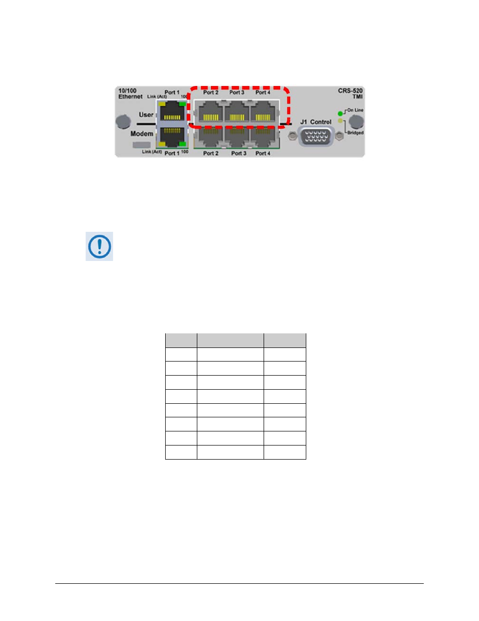
B.3.4 CRS-520 TMI – 10/100 Ethernet Connectors (RJ-45F)
The CRS-520 TMI provides four standard RJ-45F User Interface ports, operating at 10/100 Mbps,
half and full duplex, auto-negotiating for Ethernet Router Modes.
Table B-7 indicates the typical pinout for each of these connectors (10/100 Ethernet User “Port
1” through “Port 4”).
User Port 1 is reserved for use as the CRS-500 Ethernet System Communication
connection between the CRS-500 and the modems.
To avoid Ethernet Networking loops, CDM-625s operating in IP Packet Processor
Router Mode use only a single port of the CDM-625’s remaining available ports
(i.e., “Port 2” OR “Port 3” OR “Port 4”) to convey traffic data for each modem at
any given time.
Table B-7. 10/100 Ethernet Connector Pinout (Typical)
Pin #
Signal Function
Direction
1
Tx+
Tx only
2
Tx-
Tx only
3
Rx+
Rx only
4
N/C
–
5
N/C
–
6
Rx-
Rx only
7
N/C
–
8
N/C
–
- CDD-880 (124 pages)
- CDM-800 (130 pages)
- ODMR-840 (184 pages)
- CDM-750 (302 pages)
- CDM-840 (244 pages)
- SLM-5650A (420 pages)
- CTOG-250 (236 pages)
- CDM-700 (256 pages)
- CDM-760 (416 pages)
- CDM-710G (246 pages)
- CDM-600/600L (278 pages)
- CDMR-570L (512 pages)
- CDM-625 (684 pages)
- CDM-625A (756 pages)
- CDD-564A (240 pages)
- CDD-564L (254 pages)
- CLO-10 (134 pages)
- MCED-100 (96 pages)
- CDMR-570AL (618 pages)
- CDM-600 LDPC (2 pages)
- BUC Power Supply Ground Cable (2 pages)
- MPP70 Hardware Kit for CDM-570L (4 pages)
- MPP50 Hardware Kit for CDM-570L (4 pages)
- CDM-625 DC-AC Conversion (4 pages)
- CDM-625 DC-AC Conversion with IP Packet Processor (4 pages)
- DMDVR20 LBST Rev 1.1 (117 pages)
- DMD2050E (212 pages)
- DMD-2050 (342 pages)
- DMD1050 (188 pages)
- OM20 (220 pages)
- QAM256 (87 pages)
- DD240XR Rev Е (121 pages)
- MM200 ASI Field (5 pages)
- DM240-DVB (196 pages)
- MM200 (192 pages)
- CRS-150 (78 pages)
- CRS-280L (64 pages)
- CRS-170A (172 pages)
- CRS-180 (136 pages)
- SMS-301 (124 pages)
- CiM-25/8000 (186 pages)
- CiM-25 (26 pages)
- CRS-311 (196 pages)
- CIC-20 LVDS to HSSI (26 pages)