1 csu front panel – Comtech EF Data CRS-500 User Manual
Page 32
CRS-500 1:N Redundancy System
Revision 2
Introduction
MN-CRS500
1–6
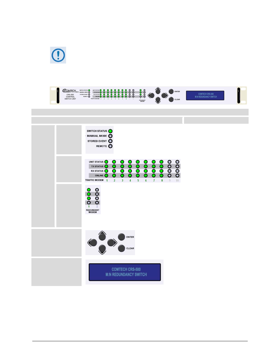
1.3.1.1 CSU Front Panel
Monitor and Control (M&C) of the complete CRS-500 system is accomplished
through the CSU. DO NOT DIRECTLY CONNECT TO A MODEM FOR REMOTE (SERIAL
OR ETHERNET) M&C.
See Chapter 5. CSU FRONT PANEL OPERATION for details on CRS-500 operations using the 1RU
CSU front panel (Figure 1-4).
CRS-500 Control Switch Unit (CSU) Front Panel Features
Feature
Description
LED
Indicators
Group
Switch
Status
Four LEDs show the operating
state of the CRS-500 System.
Traffic
Modem
Status
10 sets of four LEDs + the active
Traffic Modem number show the
operating state of up to 10 Traffic
modems.
Redundant
Modem
Status
Two sets of four LEDs + the active
Redundant Modem number show
the operating state of the
Redundant Modem.
(Note: Only RM 1 is operational.
RM 2 is reserved for future 2:N
functionality.)
Keypad
Use the six keys on the keypad to
move through menu selections.
The keys “click” to give tactile
feedback.
Vacuum Fluorescent
Display (VFD)
The VFD is an active display
showing two lines of 24 characters
each. You can control the
brightness of its blue light.
Figure 1-4. CRS-500 CSU Front Panel