Figure 3-1 – Comtech EF Data CRS-500 User Manual
Page 54
CRS-500 1:N Redundancy System
Revision 2
Installation
MN-CRS500
3–2
the unit outward to permit convenient access to the RMIs/TMIs for cable connections between
the DSU, CSU, ISUs, and the modems.
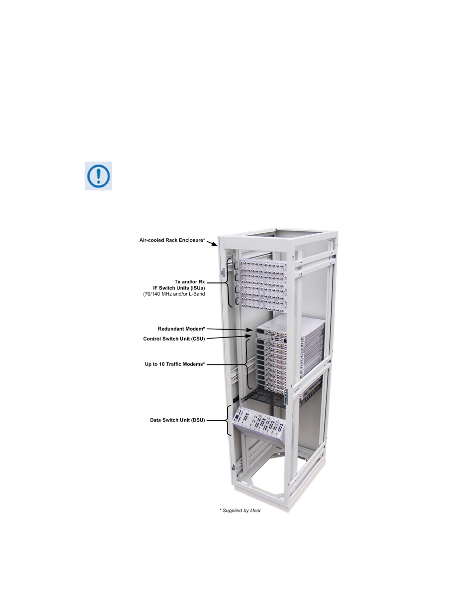
One to four optional CRS-282xx IF Switch Units (ISUs) mount into the back or on top of the rack.
For any arrangement, it is important to ensure that there is adequate clearance for ventilation in
the rack. Since the Switch itself is relatively passive, no additional clearance is needed between
it and the nearest modem. In rack systems where there is high heat dissipation, provide forced
air cooling by installing top- or bottom-mounted fans or blowers.
Do not allow the internal rack temperature to exceed 50°C (122° F).
Once all CRS-500 1:N Redundancy System components have been installed, the configuration is
now ready to be interconnected as specified in Chapter 4. CABLES
AND
CONNECTIONS.
Figure 3-1. CRS-500 Rack-Mounted Configuration Example
(Rack back view: Bottom Mount DSU, 10 TMs, four ISUs shown)