2 csu rear panel – Comtech EF Data CRS-500 User Manual
Page 33
CRS-500 1:N Redundancy System
Revision 2
Introduction
MN-CRS500
1–7
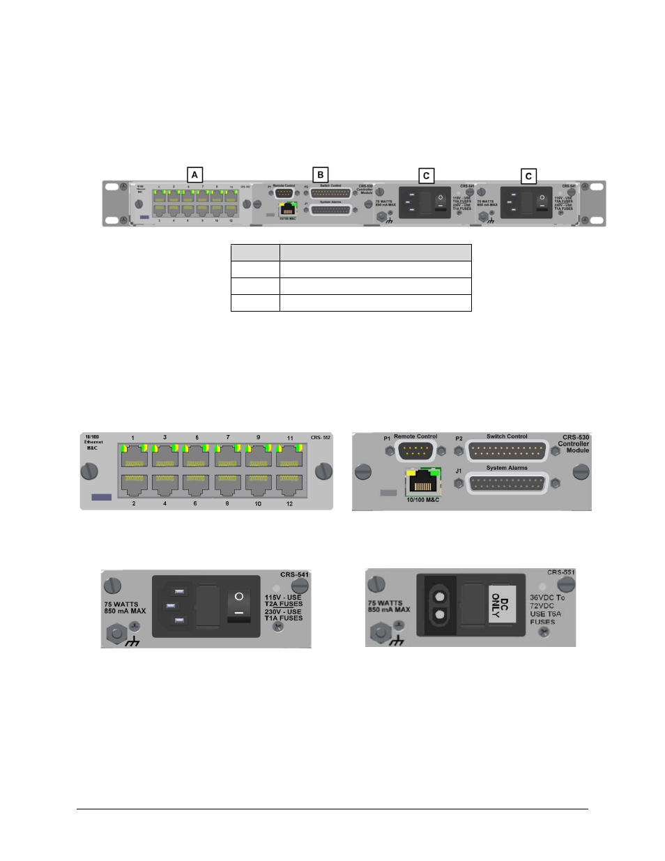
1.3.1.2 CSU Rear Panel
The CRS-500 power supplies and controller modules are located on the CSU rear panel (Figure
Feature Description
A
CRS-512 Ethernet M&C Interface
B
CRS-530 System Controller Module
C
Standard CRS-541 AC Power Supply
Figure 1-5. CRS-500 CSU Rear Panel Configuration Example
1.3.1.2.1
CSU Rear Panel System Controller, M&C, and Power
Supply Modules
DB-9M
DB-25M
RJ-45
HD-44 F
Figure 1-6. CRS-512 Ethernet M&C Module
Figure 1-7. CRS-530 System Controller Module
Figure 1-8. CRS-541 AC Power Supply
Figure 1-9. CRS-551 DC Power Supply (Optional)
See also other documents in the category Comtech EF Data Equipment:
- CDD-880 (124 pages)
- CDM-800 (130 pages)
- ODMR-840 (184 pages)
- CDM-750 (302 pages)
- CDM-840 (244 pages)
- SLM-5650A (420 pages)
- CTOG-250 (236 pages)
- CDM-700 (256 pages)
- CDM-760 (416 pages)
- CDM-710G (246 pages)
- CDM-600/600L (278 pages)
- CDMR-570L (512 pages)
- CDM-625 (684 pages)
- CDM-625A (756 pages)
- CDD-564A (240 pages)
- CDD-564L (254 pages)
- CLO-10 (134 pages)
- MCED-100 (96 pages)
- CDMR-570AL (618 pages)
- CDM-600 LDPC (2 pages)
- BUC Power Supply Ground Cable (2 pages)
- MPP70 Hardware Kit for CDM-570L (4 pages)
- MPP50 Hardware Kit for CDM-570L (4 pages)
- CDM-625 DC-AC Conversion (4 pages)
- CDM-625 DC-AC Conversion with IP Packet Processor (4 pages)
- DMDVR20 LBST Rev 1.1 (117 pages)
- DMD2050E (212 pages)
- DMD-2050 (342 pages)
- DMD1050 (188 pages)
- OM20 (220 pages)
- QAM256 (87 pages)
- DD240XR Rev Е (121 pages)
- MM200 ASI Field (5 pages)
- DM240-DVB (196 pages)
- MM200 (192 pages)
- CRS-150 (78 pages)
- CRS-280L (64 pages)
- CRS-170A (172 pages)
- CRS-180 (136 pages)
- SMS-301 (124 pages)
- CiM-25/8000 (186 pages)
- CiM-25 (26 pages)
- CRS-311 (196 pages)
- CIC-20 LVDS to HSSI (26 pages)