1 control switch unit (csu) configurations, 2 data switch unit (dsu) configurations, 3 isu (crs-282xx) specifications – Comtech EF Data CRS-500 User Manual
Page 45
CRS-500 1:N Redundancy System
Revision 2
Introduction
MN-CRS500
1–19
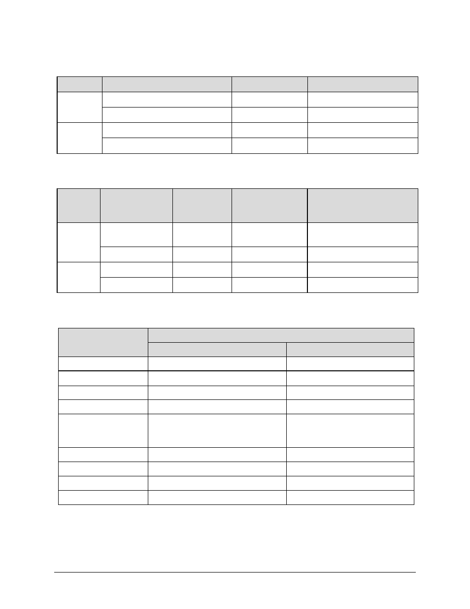
1.4.1.1 Control Switch Unit (CSU) Configurations
Modem
Terrestrial Interface
Mode of Operation
Modem to CSU Comms Module
CDM-625
EIA-422/530, V.35, Sync EIA-232
Any
CRS-512
IP Packet Processor
Layer 3 or Bridge
N/A (through TMI)
CDM-750
G.703 (T3, E3, STS-1)
Any
CRS-512
GigE Copper
Any
N/A (through TMI)
1.4.1.2 Data Switch Unit (DSU) Configurations
Modem
Terrestrial Interface
Mode of
Operation
Redundant
Modem Interface
(RMI)
Traffic
Modem Interface
(TMI)
CDM-625
EIA-422/530, V.35,
Sync EIA-232
Any
CRS-510
CRS-316
IP Packet Processor
Layer 3 or Bridge
CRS-510
CRS-520
CDM-750
G.703 (T3, E3, STS-1)
Any
CRS-505
CRS-345
GigE Copper
Any
CRS-505
CRS-516
1.4.1.3 ISU (CRS-282xx) Specifications
Characteristic
Requirement
70/140 MHz
L-Band
Operating Frequency
50 to 180 MHz
950 to 2150 MHz
Connector Type
Type ‘BNC’ 50 / 75Ω
Type ‘N’ 50Ω
Return Loss
18 dB
<12 dB
Rx-Rx Isolation
> 60 dB
> 60 dB
Tx-Tx Isolation
> 60 dB
> 60 dB (950 to 1450 MHz)
> 55 dB (1450 to 1750 MHz)
> 50 dB (1750 to 2150 MHz)
Tx Insertion Loss
< 1.5 dB
< 4.5 dB
Tx Flatness
< 0.5 dB
0.5 dB
Rx Insertion Loss
< 5 dB
< 8.5 dB
Rx Flatness
< 0.5 dB
0.5dB