Chapter 7, 1 front panel overview, Chapter 7. csu front panel operation – Comtech EF Data CRS-500 User Manual
Page 117
7–1
Chapter 7.
CSU FRONT PANEL OPERATION
7.1
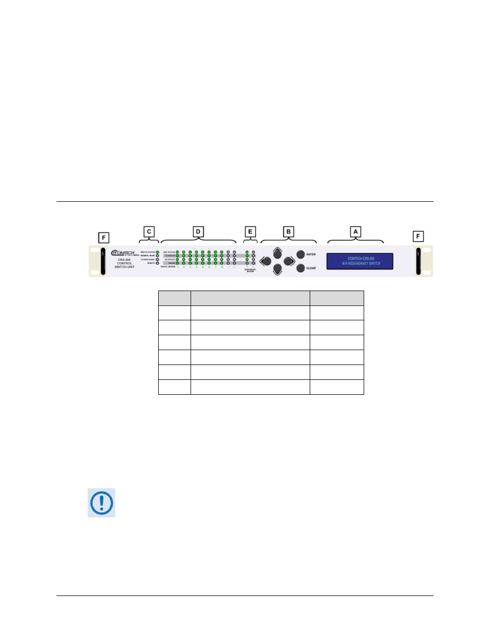
Front Panel Overview
Feature Description
Chapter Sect.
A
Video Fluorescent Display (VFD)
7.1.1
B
6-Button Keypad
7.1.2
C
Switch Status LED Group
7.1.3.1
D
Traffic Modem Status LED Group
7.1.3.2
E
Redundant Modem Status LED Group
7.1.3.3
F
Rack Handles
N/A
Figure 7-1. CRS-500 Control Switch Unit (CSU) Front Panel
Use the Control Switch Unit (CSU) front panel keypad and display to fully monitor and control
the operation of the CRS-500. The CRS-500 uses nested menus that display all available options;
the displayed messages and prompts guide you to use the keypad to carry out a required action.
Figure 7-1 identifies the control and operation features for the CRS-500 CSU, and the sections in
this chapter that explain these features in detail.
In addition to monitor and control via the CSU front panel, operation of the CRS-500
1:N Redundant System is also available via the Ethernet (i.e., SNMP, Telnet, or
HTTP) and Serial Remote interfaces. See Chapter 8. ETHERNET-BASED REMOTE
PRODUCT MANAGEMENT or Chapter 9. SERIAL-BASED REMOTE PRODUCT
MANAGEMENT, respectively, for further information.