1 status | monitor – Comtech EF Data CRS-500 User Manual
Page 154
CRS-500 1:N Redundancy System
Revision 2
Ethernet-Based Remote Product Management
MN-CRS500
8–16
8.5.3.3 Status pages
Select the Monitor or Event Log tab to continue.
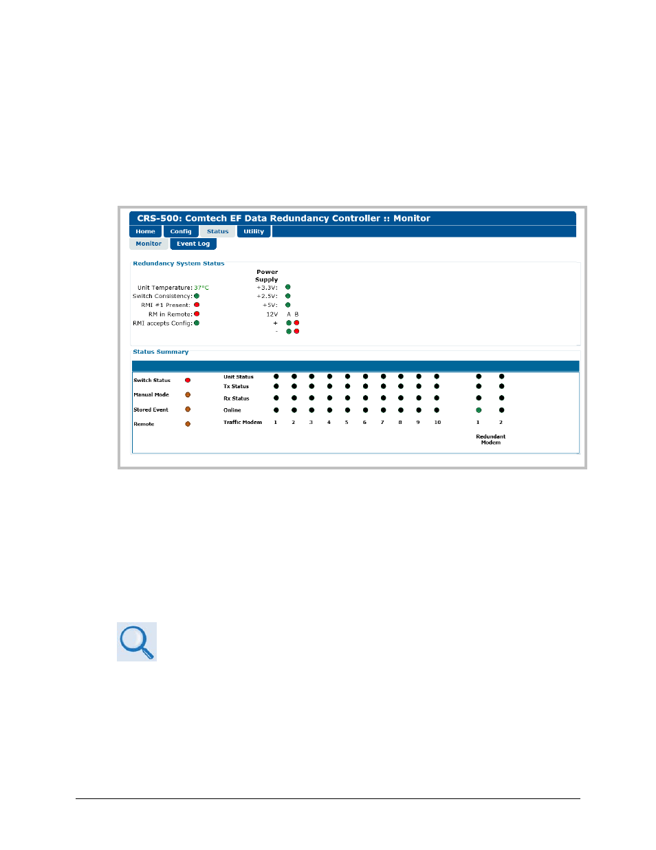
8.5.3.3.1 Status | Monitor
Use this page to view read-only status windows for the active 1:N redundancy system.
Figure 8-5. Status | Monitor Page
Redundancy System Status
The CRS-500 Data Switch Unit (DSU) status indicators in this section specify GREEN for normal
operation, or RED for fault conditions for the operating temperature, switch operation
parameters, configured redundant modem(s), and the dual power supplies.
Status Summary
Chapter 7. CSU FRONT PANEL OPERATION
This section emulates the CRS-500 Control Switch Unit (CSU) front panel LED array.
See also other documents in the category Comtech EF Data Equipment:
- CDD-880 (124 pages)
- CDM-800 (130 pages)
- ODMR-840 (184 pages)
- CDM-750 (302 pages)
- CDM-840 (244 pages)
- SLM-5650A (420 pages)
- CTOG-250 (236 pages)
- CDM-700 (256 pages)
- CDM-760 (416 pages)
- CDM-710G (246 pages)
- CDM-600/600L (278 pages)
- CDMR-570L (512 pages)
- CDM-625 (684 pages)
- CDM-625A (756 pages)
- CDD-564A (240 pages)
- CDD-564L (254 pages)
- CLO-10 (134 pages)
- MCED-100 (96 pages)
- CDMR-570AL (618 pages)
- CDM-600 LDPC (2 pages)
- BUC Power Supply Ground Cable (2 pages)
- MPP70 Hardware Kit for CDM-570L (4 pages)
- MPP50 Hardware Kit for CDM-570L (4 pages)
- CDM-625 DC-AC Conversion (4 pages)
- CDM-625 DC-AC Conversion with IP Packet Processor (4 pages)
- DMDVR20 LBST Rev 1.1 (117 pages)
- DMD2050E (212 pages)
- DMD-2050 (342 pages)
- DMD1050 (188 pages)
- OM20 (220 pages)
- QAM256 (87 pages)
- DD240XR Rev Е (121 pages)
- MM200 ASI Field (5 pages)
- DM240-DVB (196 pages)
- MM200 (192 pages)
- CRS-150 (78 pages)
- CRS-280L (64 pages)
- CRS-170A (172 pages)
- CRS-180 (136 pages)
- SMS-301 (124 pages)
- CiM-25/8000 (186 pages)
- CiM-25 (26 pages)
- CRS-311 (196 pages)
- CIC-20 LVDS to HSSI (26 pages)