Table 4-11, Table 4-10, Table 4-10. status register bits – AMETEK ASD Series User Manual
Page 77: Table 4-11. fault_bits register
Sorensen ASD Series
Programming: Digital Interface Control
M551177-01 Rev A
4-19
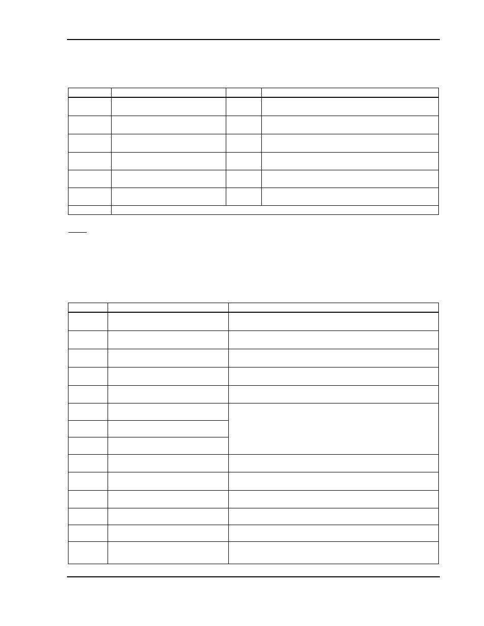
Table 4-10. Status Register Bits
Bit
Field
Value
Description
1
STATUS_BIT_ON
0
1
The unit is off.
The unit is on.
2
STATUS_BIT_FAULT
0
1
No faults.
There is a fault.
3
STATUS_BIT_ANALOG_PROG
0
1
The unit is not enabled through analog programming.
The unit is enabled through analog programming.
4
STATUS_BIT_MODBUS_PROG
0
1
The unit is not enabled through Modbus programming.
The unit is enabled through Modbus programming.
5
STATUS_BIT_IMODE
0
1
The unit is not in current mode.
The unit is in current mode.
6
STATUS_BIT_VMODE
0
1
The unit is not in current mode.
The unit is in voltage mode.
7-16
Not used
Notes:
1.
If both voltage and current mode signals are “1” this indicates that the unit is in power/process mode.
2.
The fault bit will stay high until the Command register COMMAND_BIT_RESET_FAULT bit is set to “1”.
3.
In case of a fault, the Fault_Bits will show the reason of the fault with an error code. Each fault is indicated by one bit so that
multiple faults can be indicated simultaneously. Use the Fault_Bits descriptions below to decode which fault(s) are being
annunciated.
Table 4-11. Fault_Bits Register
Code
Name
Description
0x1
FAULT_MODULE_FAULT
One or more modules have reported a fault.
0x2
FAULT_OUTPUT_IMPEDANCE
The output impedance has exceeded the maximum or is below of
minimum limit.
0x4
FAULT_COMMAND_ERROR
The unit reports that it cannot accomplish with the programmed current,
voltage and power.
0x8
FAULT_MASTER_HARD_FAULT
The master board has detected a hardware fault.
0x10
FAULT_MASTER_SUPERVISORY
The master board has detected a fault in the variables of supervision.
0x20
FAULT_ANALOG_PSETPOINT
When using 4-20mA analog programming, this signal indicates that the
input current is below 2mA. This may indicate an external problem with
the 4-20mA loop.
0x40
FAULT_ANALOG_ISETPOINT
0x80
FAULT_ANALOG_VSETPOINT
0x100
FAULT_REMOTE_SNS_ERROR
There is too much measurement error in remote sensor. This may
indicate an external problem with the remote sensing cable.
0x200
FAULT_MODBUS_TIMEOUT
No Modbus communication activity has been detected. This may
indicate an external problem with the master Modbus device.
0x400
FAULT_MASTER_WARNING
The master board has detected a warning in the variables of
supervision.
0x800
FAULT_NO_RESPONSE_MODULE
One or more modules did not respond to the internal communication.
0x1000
FAULT_REPEATED_MODULE_ID
The master has more than one module connected with the same ID
value.
0x2000
FAULT_TOO_MANY_MODULES
The master is connected to more than the maximum of 32 modules.
This may indicate that too many power supplies are connected in
parallel.