AMETEK ASD Series User Manual
Page 30
Installation
Sorensen ASD Series
2-32
M551177-01 Rev A
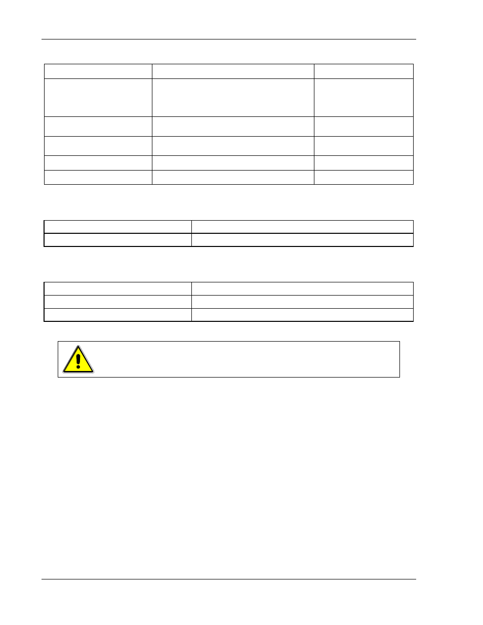
Table 2-4. Input/Output Connectors
Connector
Function
Connects To
FL1
– AC
FL1
– AC
FL1
– AC
Chassis - GND
Prime AC Power Input
See Table 2-5.
Not phase rotation sensitive. Neutral not
used.
380/400 VAC (Option)
440/480 VAC (Option)
47-63 Hz, 400 Hz
Pos. Bus Bar
Neg. Bus Bar
Output Power:
(see Table 2-6)
User load(s)
ANALOG CONTROL
Connector (J1)
Control Interface
See 3.3.5 for description
Sense Connector
Used for remote sense
Refer to Section 3.7
Parallel In-Out
Used for parallel operation
Refer to Section 3.9
Table 2-5. Input Connections
Connection
Description
Input AC connector
Feed through high current terminal block
Table 2-6. Output Connections
Connection
Description
Bus Bar
Bus Bar with two holes for each potential terminal 3/8”.
Module terminals
Output terminals with holes for 3/8" bolts (40V-60V)
CAUTION!
Prevent damage to the unit: follow torque specifications, use correct size
wire ferrule (if used), and proper size ferrule crimping tool.
T
ORQUE
S
PECIFICATIONS
The unit’s Phoenix Connectors require 18 in-lb to 20 in-lb (2 Nm to
2.3 Nm) torque.
Wire ferrules are recommended; their size must match the wire
gauge.
Crimp tool size must be appropriate to the ferrule size.
Wire insulation should be stripped back no more than 5/8 inch for the
ferrule.
For more information on this AC input connector, please look up Phoenix
Contact part number HDFKV 16 at www.phoenixcontact.com.