AMETEK ASD Series User Manual
Page 72
Programming: Digital Interface Control
Sorensen ASD Series
4-14
M551177-01 Rev A
Notes:
1.
All the registers have integer data. IQ means fractional notation:
o
IQ15 means that the desired real value has to be multiplied by 2
15
, for example 0.5 equals to 16384 in IQ15.
o
IQ10 means that the desired real value has to be multiplied by 2
10
.
2.
32-bit registers are composed of two 16-bit registers, HI (16 MSB) and LO (16 LSB)
3.
See Fault_Bits for the bit codes and descriptions.
For a 3-module unit, the maximum voltage is 1.0, the maximum current is 3.0 and the maximum power is 3.0.
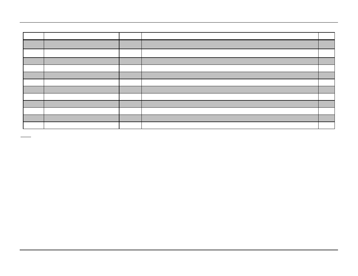
Address
Name
IQ
Description
Notes
43, 44
Vlimit_HI/LO
IQ15 / FP
Artificial limit of voltage setpoint. Changing this value will change the scaling of the analog inputs and
outputs. 1.0 = nominal voltage (60V / 40V).
45, 46
Ilimit_HI/LO
IQ15 / FP
Artificial limit of current setpoint. Changing this value will change the scaling of the analog inputs and
outputs. 1.0 = nominal current of one module (167A / 250A).
47
Time_hi
Int16
Real time clock time in BCD
48
Time_md
Int16
Real time clock time in BCD
49
Time_lo
Int16
Real time clock time in BCD
3
50
Process_config
binary
Used to configure process control feature
51, 52
Process_coef_0
FP
Coefficient B2 of 2P/2Z compensator for process control
53, 54
Process_coef_1
FP
Coefficient B1 of 2P/2Z compensator for process control
55, 56
Process_coef_2
FP
Coefficient B0 of 2P/2Z compensator for process control
3
57, 58
Process_coef_3
FP
Coefficient A2 of 2P/2Z compensator for process control
59, 60
Process_coef_4
FP
Coefficient A1 of 2P/2Z compensator for process control
61
Ethercat_config
binary
Used to configure EtherCAT interface (disable)