1 isolated analog interface connections – AMETEK ASD Series User Manual
Page 27
Sorensen ASD Series
Installation
M551177-01 Rev A
2-29
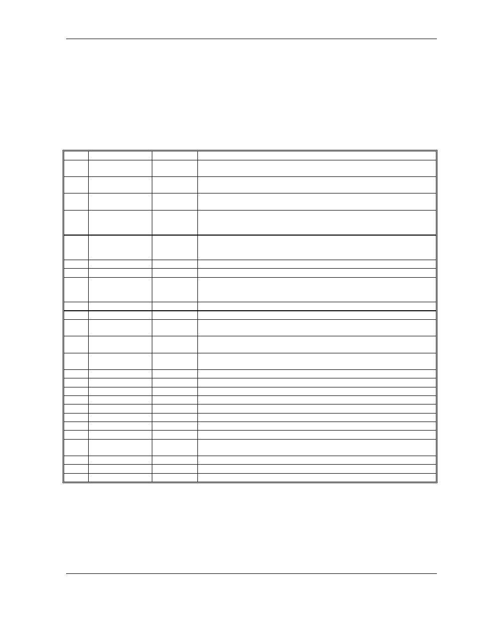
2.5.1 ISOLATED ANALOG INTERFACE CONNECTIONS
Table 2-1 and Table 2-2 describe the available input and output signals at
the DB25 connectors for standard ASD units and the SG compatible
interface. Table 2-3 describes the available input and output signals at the
DB9 connector for ASD units with the EtherCAT interface option. Section
2.9 provides a drawing of the rear panel input/output connector locations.
Table 2-1. Analog Interface Signals. Standard ASD Pin-out (DB25)
PIN #
PIN NAME
IN/OUT
DESCRIPTION
1
I_MON
A/OUT
a 0-10 VDC monitor signal (or 4-20 mADC) that indicates zero to full scale
output current
2
V_MON
A/OUT
a 0-10 VDC monitor signal (or 4-20 mADC) that indicates zero to full scale
output voltage
3
P_MON
A/OUT
a 0-10 VDC monitor signal (or 4-20 mADC) that indicates zero to full scale
output power
4
V_MODE
D/OUT (*)
LO indicates the unit is not in voltage mode, HI indicates the unit is in
voltage mode if I_MODE is low. If both I_MODE and V_MODE are HI, it
means power mode.
5
I_MODE
D/OUT (*)
LO indicates the unit is not in current mode, HI indicates the unit is in
current mode if V_MODE is low. If both I_MODE and V_MODE are HI, it
means power mode.
6
STATUS
D/OUT (*)
LO indicates output disabled, HI indicates the output is enabled.
7
FAULT
D/OUT (*)
LO indicates normal operation, HI indicates a fault.
8
DOUT_REF
IN
Used to define the output high level of the digital outputs. If not
connected, the output high is 12V. If connected to 24Vdc, the output high
is 24V.
9
GND
common
Same as pin 16
10
+24Vdc
OUT
+24VDC, same as pin 17
11
I_PROG
A/IN
a 0-10 VDC analog input signal (or 4-20 mADC) that programs zero to full
scale output current
12
V_PROG
A/IN
a 0-10 VDC analog input signal (or 4-20 mADC) that programs zero to full
scale output voltage
13
P_PROG
A/IN
a 0-10 VDC analog input signal (or 4-20 mADC) that programs zero to full
scale output power
14
START/STOP
D/IN (**)
LO disables output, HI enables output.
15
RESET
D/IN (**)
LO to HI transition clears faults and warnings.
16
GND
common
Same as pin 9
17
+24Vdc
OUT
+24VDC, same as pin 10
18
GND
common
Same as pin 9
19
GND
common
Same as pin 9
20
Not used
21
Not used
22
RS-485 enable
D/IN
A high level will disable the Ethernet Interface to be able to use Modbus
over RS-485
23
RS-485 A
D/IO
Modbus interface over RS-485
24
RS-485 B
D/IO
Modbus interface over RS-485
25
RS-485 GND
common
Ground for serial interface (it is not isolated from the common ground)
Digital signal levels:
(*) Digital output low is 0V (<0.5V), output high is either 12V or 24V (+/-1V), depending
on pin 8.
(**) Digital input low is 0.5V or lower, input high is 8V or higher.