AMETEK ASD Series User Manual
Page 57
Sorensen ASD Series
Operation
M551177-01 Rev A
3-19
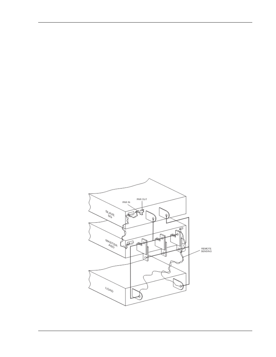
1. Beginning with the ASD power supply designated as the Master
power supply, use an interface cable (P/N 5551189-01) to connect
the ANALOG INTERFACE connector on the ASD power supply to
the PAR IN and PAR OUT connectors on the second power supply
(Slave).
2. Connect the Positive output terminals of all the power supplies and
the Load.
3. Connect the Negative output terminals of all the power supplies
and the load.
4. Confirm that there are no shorts between the Positive and
Negative output terminals.
5. Connect twisted pair cables as follows:
The slave unit shall have twisted pair from its SENSE terminals to its output
terminals, as appropriate.
For Remote Sense, the master unit shall have a twisted pair from its own
SENSE terminals to the Load’s output terminals.
For Local Sense, the master unit shall have a twisted pair from its own
SENSE terminals to its own output terminals.
Ensure that all twisted pair cables are as short as possible.
Figure 3-22. Parallel and Remote Sense Connection of ASD as Master and SG as Slave