Load considerations – AMETEK ASD Series User Manual
Page 33
Sorensen ASD Series
Installation
M551177-01 Rev A
2-35
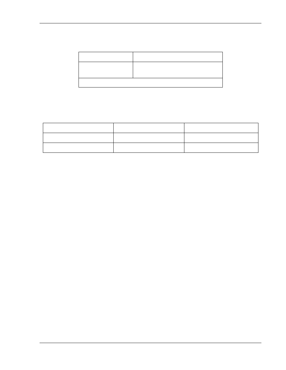
Refer to Table 2-9 for input/output lug recommendations.
Table 2-9. Recommended Lugs
Lug Manufacturer
Input/Output
Panduit
“PN” Series or equivalent
”LCAN” Series for higher current
Note: Contact lug manufacturer for recommended crimping tool.
The recommended tools for crimping and extraction of the sense
connector pins are listed below in Table 2-10.
Table 2-10. Recommended Sense Connector Tools
Tool
Manufacturer
Manufacturer P/N
Crimping
Molex
11-01-0197
Extracting
Molex
11-03-0044
2.7
LOAD CONSIDERATIONS
This section provides guidelines for using properly rated diodes to protect
the power supply from damage while driving inductive loads.
2.7.1 INDUCTIVE LOADS
To prevent damage to the power supply from inductive kickback, connect
a diode (rated at greater than the supply’s output voltage and current)
across the output. Connect the cathode to the positive output and the
anode to return. Where positive load transients such as back EMF from a
motor may occur, a second diode in series with the output is
recommended to protect the power supply.
B
LOCKING AND
F
REE
W
HEELING
D
IODES
The Peak Reverse Voltage ratings should be a minimum of 2-3 times the
Power Supply maximum output voltage. The Continuous Forward Current
ratings should be a minimum of 1.5 times the Power Supply maximum
output current. Heatsink may be required. There also may be a need for
higher voltage rated parts, dependent on load circuit design and inductor
values.