Operation, Introduction, Front panel – AMETEK ASD Series User Manual
Page 39
M551177-01 Rev A
3-1
SECTION 3
OPERATION
3.1
INTRODUCTION
This section begins with a description of the ASD power supply front and rear panels
and then presents the user interface for operating the power supply.
WARNING!
The power-up factory default state is output enabled.
3.2
FRONT PANEL
The ASD front panel has LEDs to indicate the status of the power supply and of the
modules.
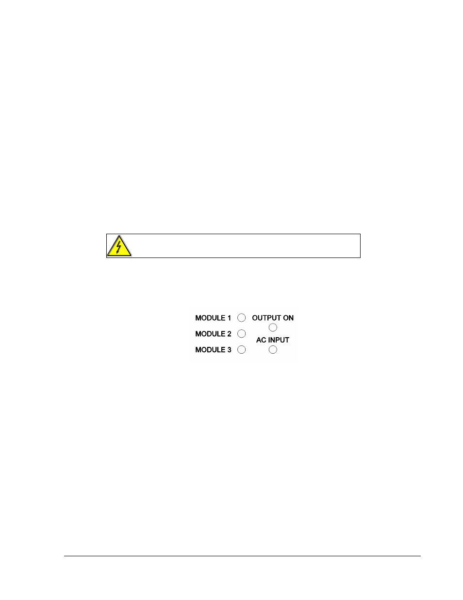
Figure 3-1. Status LEDs
The MODULE LEDs represent the modules inside the unit by location:
from the view of the front panel, MODULE 1 is located at the left side of
the unit; MODULE 2 is in the center; MODULE 3 is located at the right.
The LED labeled “AC INPUT” indicates that the unit is powered and also
shows the unit and master controller condition based on the color code.
The LED color codes for the MODULE and AC INPUT are as follows:
Green = normal condition of the module or unit.
Yellow = abnormal condition (warning or not severe fault).
Red = severe fault that shuts down the module or unit.
The LED labeled “OUTPUT ON” is green when the power supply has set the output to
active mode. If it is off it means that the internal power stages are not active.