N 3.9.2), O figure 3-21), Figure 3-21 – AMETEK ASD Series User Manual
Page 56
Operation
Sorensen ASD Series
3-18
M551177-01 Rev A
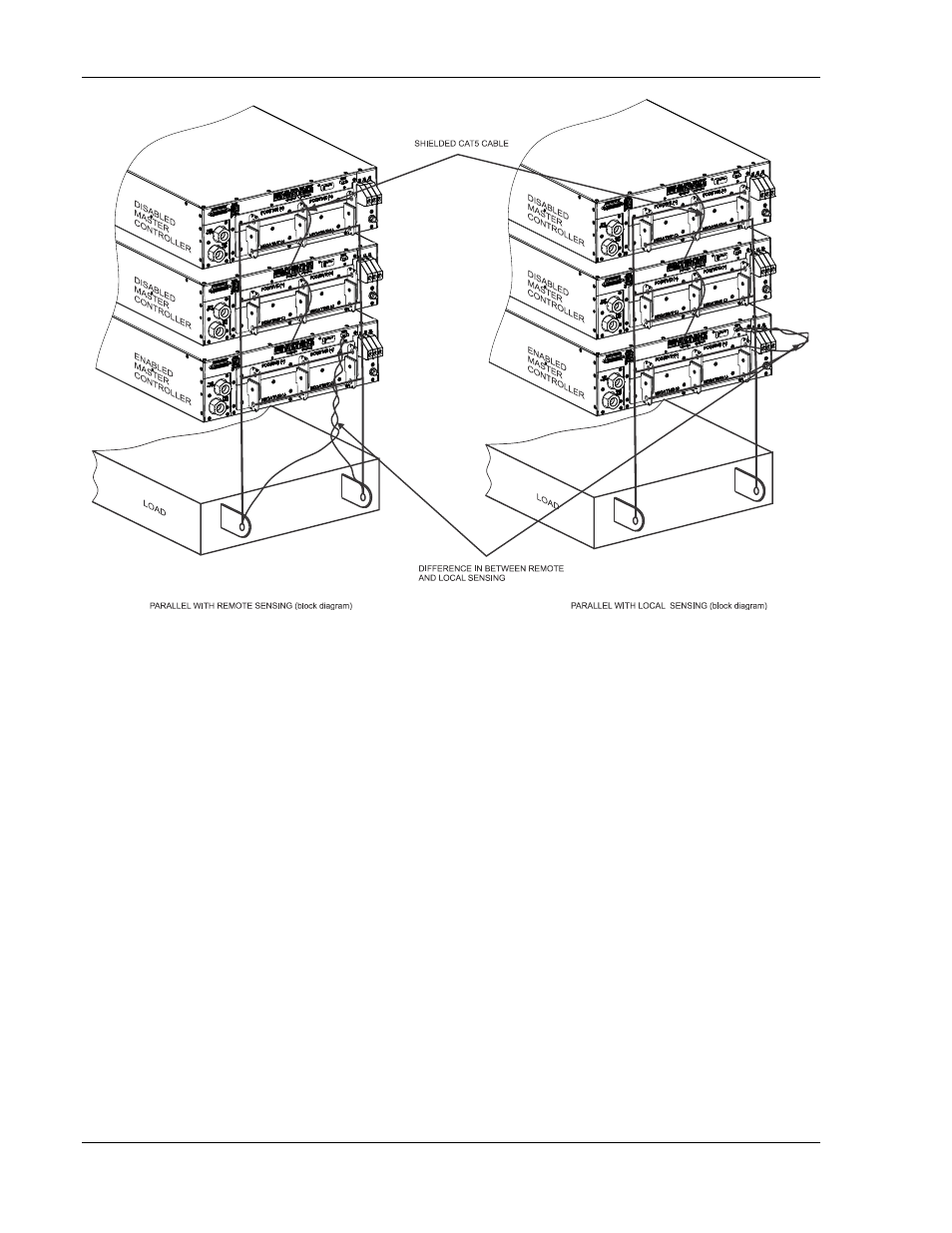
Figure 3-21. Parallel and Remote/Local Sense Connections
Note: The OVP circuit remains active for all units in parallel operation.
3.9.2 PARALLEL OPERATION WITH AN ASD UNIT AND AN SGA UNIT
The following modes of operation are used for applications requiring more
current than is available from a single power supply. To meet the
requirements for greater output current, two supplies may be connected in
parallel.
In order to connect two power supplies in parallel, use a “Master/Slave”
wiring configuration as follows (refer to Figure 3-22):
(Note that in ASD unit there is a 25-pin connector and on SG unit there are
two separate 9-pin connectors on the upper left rear panel of each power
supply, marked “ANALOG INTERFACE” and “PAR OUT” and “PAR IN”
respectively).
- CW-M (48 pages)
- CW-M Corrected Table 4-2 in (1 page)
- CW-P (62 pages)
- Lx Series (205 pages)
- CW Series Programming Manual (25 pages)
- Ls Series II Programming Manual (242 pages)
- Compact i/iX Series (157 pages)
- Compact IX 2253 (157 pages)
- Compact i/iX Series Software Manual (203 pages)
- ASD Series Quick Start (5 pages)
- i-iX Series II Programming Manual (226 pages)
- DLM 600W Series Programming Manual (24 pages)
- M131 Programming Manual (99 pages)
- DLM Series (74 pages)
- DLM 600W Series (82 pages)
- BPS Series (153 pages)
- DLM600 Series (16 pages)
- DCS-E 1.2kW Series (65 pages)
- DLM-E 4kW Series Programming Manual (32 pages)
- M136 (8 pages)
- DCS-E 3kW Series (94 pages)
- CTS 3.0 (166 pages)
- CSW Series (174 pages)
- 2003RP (126 pages)
- 2001RP (131 pages)
- MX CTSH (151 pages)
- MXCTSL Administrator Manual (27 pages)
- MX CTSL (157 pages)
- RS Series (228 pages)
- MX Series Installation Manual (35 pages)
- Ls AC source (2 pages)
- MX15 Series (184 pages)
- Ls Series II (226 pages)
- Lx Series Driver Manual (275 pages)
- MX Series Rev: AY (257 pages)
- iX Series (341 pages)
- i-iX Series II (258 pages)
- GUPS 2400A-108 (36 pages)
- HPD Series (58 pages)
- HPD Series Operation Manual (41 pages)
- HPD Series GPIB-Multichannel (134 pages)
- PLA-PLW Programming Manual (74 pages)
- ReFlex Mating Connnectors for Controller (3 pages)
- LPDC-16V (4 pages)