AMETEK ASD Series User Manual
Page 69
Sorensen ASD Series
Programming: Digital Interface Control
M551177-01 Rev A
4-11
can be accessed by using different command numbers. After the
“Query_Module” register is written with the 2 number, the master controller
will communicate with the module to obtain the data and will make it
available at the read register “Module_Query_Info_HI/LO”.
Read registers at addresses 100 to 131 have the discovered module bus
addresses required to query the module, they are sorted from lower
address to higher.
To summarize, the sequence to read module information is:
1. Find the module bus address in registers 100 to 131.
2.
Write the “Query_Module” register with the module address and the desired
command number.
3.
After a few milliseconds, read the data from the “Module_Query_Info_HI/LO”
register.
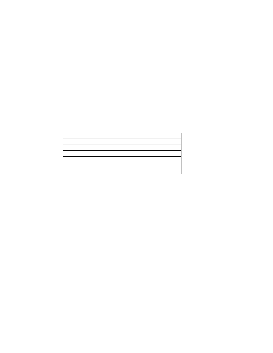
Table 4-3. Module Data Query Commands
Command number
Module data
0
Module ID
1
Firmware version
2
Serial number
3
Module status
4
Supervisory fault
5
Supervisory warning
4.3.11 PROGRAMMABLE SLEW-RATE LIMIT
The slew-rate of the output voltage and/or current can be controlled when
the
setpoints
change.
There
are
two
32bit
registers,
“Vsetpoint_SRL_HI/LO” and “Isetpoint_SRL_HI/LO”, that limit in V/ms and
A/ms the speed of change of the voltage and current setpoints. If sudden
changes in the setpoints are applied through analog or digital interface,
the master controller limits the slew-rate to the programmed limits.
4.3.12 PROGRAMMABLE LOW-PASS-FILTERS
The master controller applies a low pass filter (LPF) to the monitor signals
before making them available at the analog port and the read registers.
This LPF can be programmed to respond slower in case the load is not
constant and the average variables want to be monitored.
The digital low pass filters implemented in the master controller are single-
pole, and can be programmed with the alpha (
) coefficient, given by:
= 1/(f
c
*2
)/(1/(f
c
*2
)+1/f
s
)
Where f
c
is the desired cut off frequency, and f
s
is the sampling rate of the
digital filter, which is 125Hz for the master controller.