AMETEK ASD Series User Manual
Page 106
Programming: Digital Interface Control
Sorensen ASD Series
4-48
M551177-01 Rev A
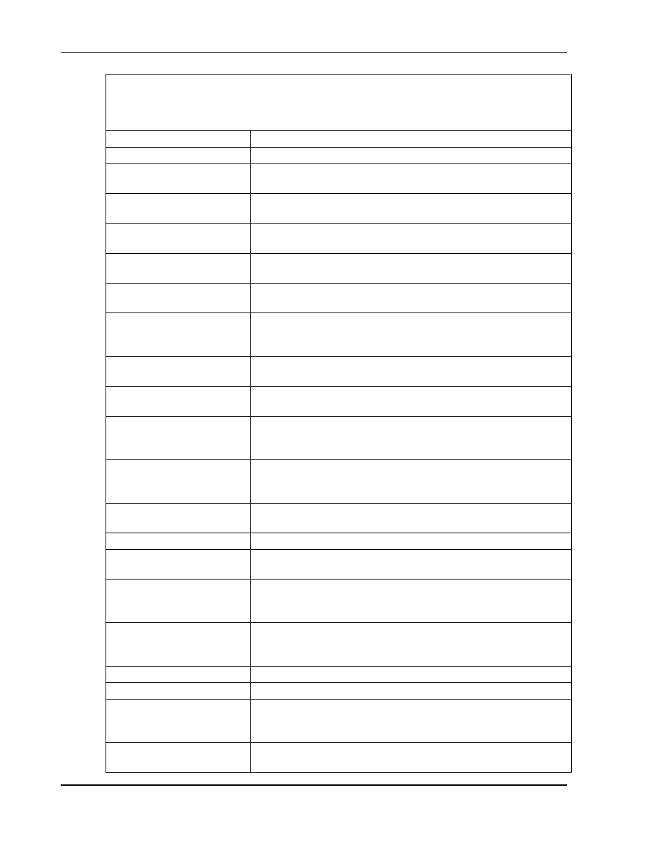
Note: If both black (true), this indicates that the power supply output is in power control
mode. If both white (false), this indicates that the power supply output is in an
unknown mode most likely caused by a setpoint of zero (see Setpoints group) or the
output being disabled.
On
Indicates that the power supply output is enabled.
Fault
Indicates that that a system fault has occurred.
DP
Indicates that the power supply setpoints are being taken
from the digital programming interface.
AP
Indicates that the power supply setpoints are being taken
from the analog programming interface
Digital Inputs group
Note: clicking the controls in the Digital Inputs group will
toggle them between black = true; white = false.
Output Enable
Enables the output of the power supply for programming
through the digital programming interface
Fault Reset
Resets any resettable system, master or module fault
conditions
Remote Sense Disable
Disables remote voltage sensing so the power supply
regulates it’s output voltage using a local voltage
measurement
Load Protection Enable
Activates the power supply load protection monitoring
which is configurable in the main window Advanced tab
Reset Energy Meter
Resets the energy meter to zero so it can begin
accumulating the total power output by the power supply
MODBUS Timeout
Enables Modbus timeout monitoring which create a fault if
there is no Modbus activity for a interval defined on the
main window Advanced Settings tab
FDR Enable
Enables the FDRs (Flight Data Recorders) in the power
supply to periodically save information about the power
supply status.
Process Enable
Enables the process control feature which allows the
power supply to control an external process.
Unit Status group
Existing modules
Indicates the number of modules existing to the power
supply master controller.
Active modules
Indicates the number of modules that are actively
outputting or prepared to output power based on master
controller commands.
Module Status
A color-coded, numbered box appears in this row for each
existing module (maximum 16 modules); red = fault; yellow
= warning; green = operating normally
Unit SN
Displays the serial number of the power supply
Unit PN
Displays the part number of the power supply
Master ID
Displays the master id bits of the power supply; if the
cursor is held over this control a tool tip will be shown
which decodes and gives descriptions of the master id bits
Master FV
Displays the firmware version of the power supply’s master
controller.