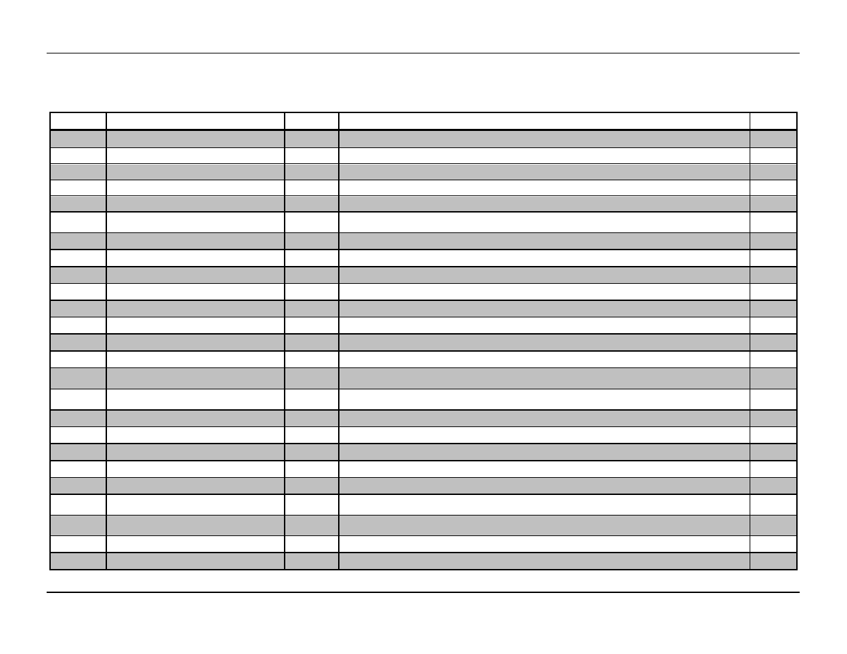
Table 4-9 – AMETEK ASD Series User Manual
Page 75
Sorensen ASD Series
Programming: Digital Interface Control
M551177-01 Rev A
4-17
Table 4-9. Read Registers
Address
Name
IQ
Description
Notes
0
Status
n/a
Describes the status of the unit (output enabled, faults, mode, etc). See register description below
1, 2
Fault_Bits_HI/LO
binary
Ssytem fault bits, each bit of the number means a different fault. See fault bits description.
3
3, 4
Vmonitor_HI/LO
IQ15 / FP
Output voltage monitor. 1.0 = nominal current of one module (167A / 250A)
1, 2
5, 6
Imonitor_HI/LO
IQ15 / FP
Output current monitor. 1.0 = nominal voltage (60V / 40V)
1
7, 8
Pmonitor_HI/LO
IQ15 / FP
Output power/process monitor. 1.0 = nominal power of one module (10020W / 10000W)
1, 2
9
Existing_Modules_Qty
Int16
Number of modules that are recognized by the unit. Depends on the number of modules that were
discovered by the master controller.
10
Active_Modules_Qty
Int16
Number of modules recognized by the master as active (functional).
11, 12
Modules_Active_HI/LO
binary
Bits in “1” indicate that the corresponding modules are active
2
13, 14
Modules_Fault_HI/LO
binary
Bits in “1” indicate that the corresponding modules have faults
2
15, 16
Modules_Warning_HI/LO
binary
Bits in “1” indicate that the corresponding modules have warnings
2
17, 18
Zoutput_HI/LO
IQ24 / FP
Load impedance monitor. 1.0 = (nominal voltage / nominal current) of one module (0.3593
/ 0.1600
)
1, 2
19, 20
Zoutput_ROC_HI/LO
IQ20 / FP
Load impedance rate-of-change monitor. Percent change per second.
1, 2
21, 22
Master_ID_HI/LO
binary
Hardware configuration of the master controller, used to identify the unit type.
2
23, 24
Serial_Number_HI/LO
Int32
Serial number of the master controller.
2
25, 26
ZCable_HI/LO
IQ15 / FP
Load cable impedance monitor. Only valid if remote sensing is enabled. 1.0 = (nominal voltage / nominal
current) of one module (0.3593
/ 0.1600
)
1, 2
27, 28
VDrop_Cable_HI/LO
IQ15 / FP
Load cable voltage drop monitor. Only valid if remote sensing is enabled. 1.0 = nominal voltage (60V /
40V)
1, 2
29, 30
Module_Query_Info_HI/LO
binary
Used to read module data, in combination with Write register 28 (Query_Module).
2
31, 32
Energy_Meter_HI/LO
Int32
Cumulative counter of energy supplied by the unit (1 = kW • s).
2, 5
33
Firmware_Version
binary
Indicates the current firmware version of the master controller.
34
Modbus_status
binary
Indicates the status history of the Modbus communication. Used for debugging Modbus communication.
35, 36
Unit_Serial_Number_HI/LO
Int32
Serial number of the unit.
37, 38
Master_Supervisory_Faults_HI/LO
binary
Master controller supervisory fault bits, each bit of the number means a different fault. See fault bits
description.
39, 40
Master_Supervisory_Warnings_HI/LO
binary
Master controller supervisory warning bits, each bit of the number means a different warning. See fault
bits description.
100 - 131
Module_Info
binary
Used to obtain information on connected modules, see register description below.
4
500 - 510
Unit_PN
char
Stores a string with the part number of the unit.