AMETEK ASD Series User Manual
Page 32
Installation
Sorensen ASD Series
2-34
M551177-01 Rev A
When determining the optimum cable specification for your power
applications, the same engineering rules apply whether going into or out of
an electrical device. Thus, this guide applies equally to the input cable
and output cable for this Sorensen instrument and application loads.
Power cables must be able to safely carry maximum load current without
overheating or causing insulation destruction. It is important to everyday
performance to minimize IR (voltage drop) loss within the cable. These
losses have a direct effect on the quality of power delivered to and from
instruments and corresponding loads.
When specifying wire gauge, consider the operating temperature. Wire
gauge current capability and insulation performance drops with the
increased temperature developed within a cable bundle and with
increased environmental temperature. Thus, short cables with generously
derated gauge and insulation properties are recommended for power
source applications.
Be careful when using published commercial utility wiring codes. These
codes are designed for the internal wiring of homes and buildings and
accommodate the safety factors of wiring loss, heat, breakdown insulation,
aging, etc. However, these codes consider that up to 5% voltage drop is
acceptable.
Such a loss directly detracts from the quality performance specifications of
this Sorensen instrument. Also, consider how the wiring codes apply to
bundles of wire within a cable arrangement.
In high performance applications requiring high inrush/ transient currents,
additional consideration is required. The cable wire gauge must consider
peak voltages and currents, which may be up to ten times the average
values. An underrated wire gauge adds losses, which alter the inrush
characteristics of the application and thus the expected performance.
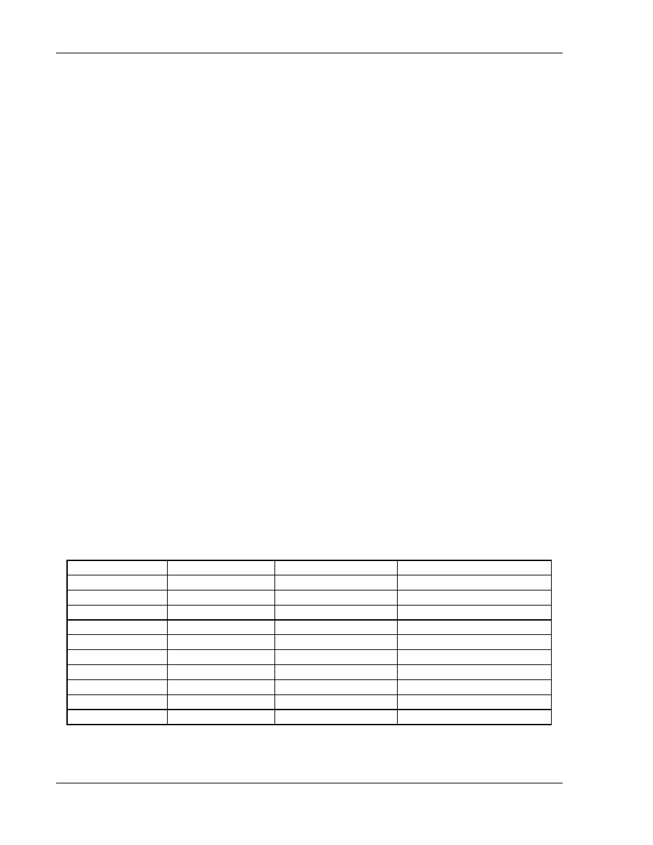
Table 2-8 presents wire resistance and resulting cable voltage drop at maximum
rated current.
Table 2-8. Wire Resistance and Voltage Drop
Column 1
Column 2
Column 3
Column 4
Size
(AWG)
Amperes
(Maximum)
Ohms/100 Feet
(One Way)
Voltage Drop/100 Feet
(Column 2 x Column 3)
14
20
0.257
5.14
12
25
0.162
4.05
10
30
0.102
3.06
8
40
0.064
2.56
6
55
0.043
2.36
4
70
0.025
1.75
2
95
0.015
1.42
1/0
125
0.010
1.25
3/0
165
0.006
1.04
Refer to Section 1.2.2 for AC input and output current requirements.