AMETEK ASD Series User Manual
Page 29
Sorensen ASD Series
Installation
M551177-01 Rev A
2-31
2.5.2 EXTERNAL SWITCHES
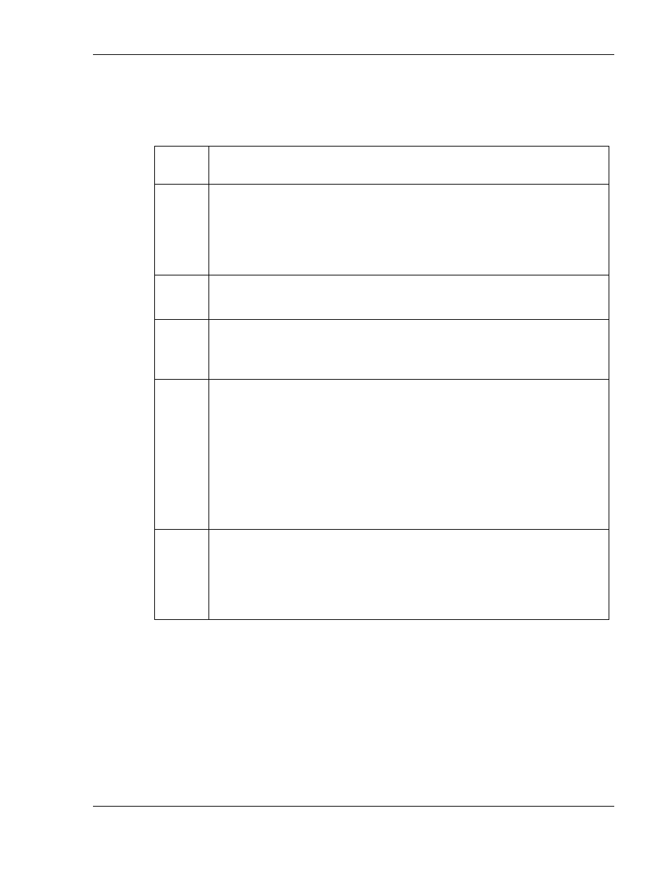
The eight position DIP switch labeled DGTL SETUP is used for power
supply configuration. The following table lists each position and its
function:
Switch
number Description
1
DOWN (on) = 0
– 10 VDC monitor signals and analog programming
references
UP (off) = 4
– 20 mADC monitor signals and analog programming
references. If the input current is lower than 2 mA, the unit will generate
a fault.
2
DOWN (on) = remote voltage sense disabled.
UP (off) = remote voltage sense enabled.
3
DOWN (on) = master enabled (sets the master as active).
UP (off) = master disabled (the modules in the chassis will operate with
an external master).
4 to 7
Unit address or expected number of modules, depending on switch
8.Use these switches to define a binary number from 0 to 15 (1111 in
binary), switch 4 is the least significant bit and switch 7 the most
significant.
DOWN (on) is a binary ZERO
UP (off) is a binary ONE
The unit address or expected number of modules will be the binary
value plus one (giving a range of 1 to 16).
8
DOWN (on) = switches 4-7 are used to set the unit address, necessary
for the digital interface.
UP (off) = switches 4-7 are used to indicate the power supply how many
modules it should expect to discover. For more details please see the
description of the expected number of modules feature.