Technical description, 1 factory calibration and adjustment, 2 over current protection – BINDER CB 60 User Manual
Page 130: 3 definition of usable volume
CB (E6) 09/2013
Page 130/144
22. Technical description
22.1 Factory calibration and adjustment
This unit was calibrated and adjusted in the factory. Calibration and adjustment were performed using
standardized test instructions, according to the QM DIN EN ISO 9001 system applied by BINDER
(certified since December 1996 by TÜV CERT). All test equipment used is subject to the administration of
measurement and test equipment that is also a constituent part of the BINDER QM DIN EN ISO 9001
systems. They are controlled and calibrated to a DKD-Standard at regular intervals.
A record of this calibration and adjustment is part of the BINDER test certificate of the unit.
Adjustment in factory:
•
Temperature: 37 °C / 98.6°F measured in the center of the usable volume
•
CO
2
: 0 vol.-% CO
2
(100 vol.-% N
2
) and 5 vol.-% CO
2
(analyzed test gas directly exposed to the sensor
head)
•
O
2
(unit with O
2
control): 0 vol.-% O
2
(100 vol.-% N
2
, analyzed test gas directly exposed to the sensor
head) and 20.9 vol.-% O
2
(ambient air).
•
Humidity: Ambient humidity and maximum humidity ion equilibrated state
Repeated calibrations are recommended in periods of 12 months.
BINDER service uses an electronic measuring and display device for temperature traceable to an
acknowledged standards/calibration institution (DKD or PTB for Germany) with valid calibration certificate.
Test gases with an analyzed concentration serve to calibrate the sensor systems for CO
2
and O
2
(unit
with O
2
control). The sensor heads are exposed directly to the test gas.
22.2 Over current protection
The CB is protected by a unit-protection against over current, accessible from the outside. It is located at
the rear of the chamber below the strain relief of the power cord. The fuse holder is equipped with a fuse
clip 5mm x 20 mm (cUL-Version 6.3 x32 mm). Replace this fuse only with a substitute of the same
ratings. Refer to the technical data of the respective device type. If this fuse is blown, please inform an
electronic engineer or BINDER service.
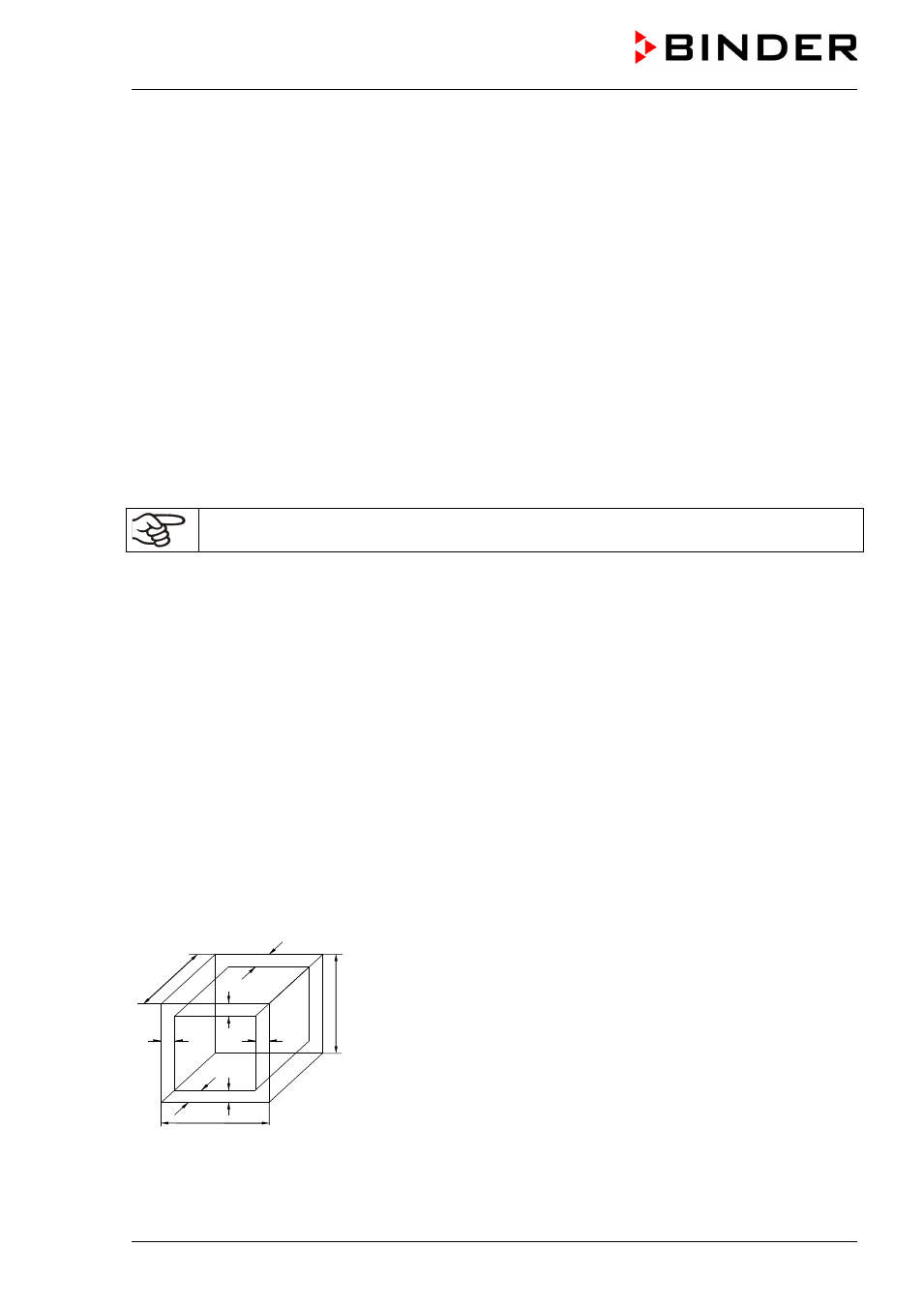
22.3 Definition of usable volume
The usable volume illustrated below is calculated as follows:
b
c
c
b
a
C
B
A
a
A, B, C = internal dimensions (W, H, D)
a, b, c = wall separation
a = 0.1*A
b = 0.1*B
c = 0.1*C
V
USE
= (A - 2 * a) * (B - 2 * b) * (C - 2 * c)
Figure 28: Determination of the usable volume
The technical data refers to the defined usable volume.