EVCO c-pro CLIMA sistema Installer manual User Manual
Page 60
C-PRO CLIMA SISTEMA INSTALLER MANUAL
Page 60
8.3.2
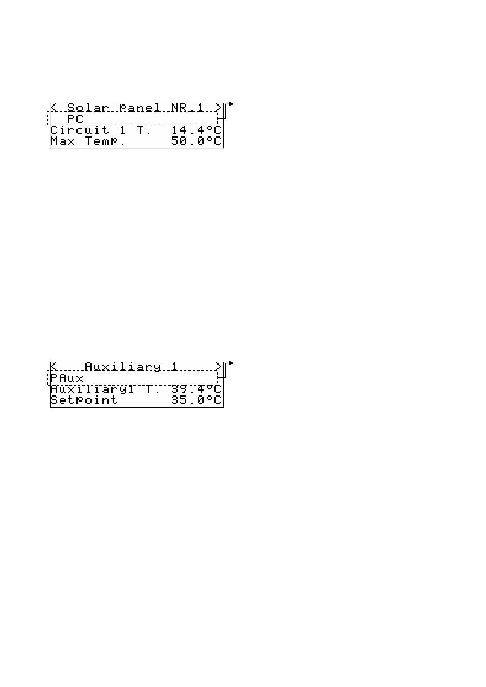
Functioning state of solar panels circuit 1 and 2
The functioning state page of the solar panels circuits 1 and 2 will contain the following
information:
The state page of the solar panels circuit 1-2 shows, as well as the state of the line described in the
previous illustration, the temperature of the water in the solar panels circuit and the maximum
temperature accepted before the high temperature alarm is signalled
Pressing ENTER on the “>” access the next state page, corresponding with the SOLAR PANELS
CIRCUIT 2.
By pressing ENTER on the “<” access the previous state page, i.e. the DHW CIRCUIT state page.
When the 60 seconds time-out has passed or by pressing ESC, the controller will go back to the
display of the main ON page.
8.3.3
Functioning state of auxiliary circuit
The auxiliary circuit state page will contain the following information:
The state page of the auxiliary circuit shows, as well as the state of the line described in the
previous illustration, the temperature of the water of the auxiliary circuit and its work set-point set.
Pressing ENTER on the “>” access the next initial state page, corresponding with the DHW
CIRCUIT.
By pressing ENTER on the “<” access the previous state page, i.e. the SOLAR PANELS 2 state
page.
When the 60 seconds time-out has passed or by pressing ESC, the controller will go back to the
display of the main ON page.
Line indicating the state of solar panels circuit 1 and 2 (PS1 and 2):
P1-2 = PS 1-2 circuit circulation pump activated
PC = PS 1-2 circuit circulation pump activated for periodic cycle
Alr = PS 1-2 circuit circulation pump thermal switch alarm
FL = PS 1-2 line flow switch alarm with automatic rearm
FL* = PS 1-2 line flow switch alarm with manual rearm
LT = PS 1-2 line low water temperature alarm
HT = PS 1-2 line high water temperature alarm
Ag = PS 1-2 circuit antigrip function active
Mn = PS1-2 circ. pump functioning in manual mode
Line indicating the state of the auxiliary circuit (Aux1):
PAux = Aux1 circulation pump activated
Alr = Aux1 circulation pump heat alarm
FL = Aux1 line flow switch alarm with automatic rearm
FL* = Aux1 line flow switch alarm with manual rearm
LT = Aux1 line low water temperature alarm
HT = Aux1 line high water temperature alarm
Ag = Aux1 circuit Antigrip function active
Mn = PS1-2 circ. pump functioning Aux1 in manual mode