Elecraft K3 Assembly Manual User Manual
Page 67
66
Install the rear bottom cover section as follows (see Figure 93):
Position the cover so the holes near the center line up with the transistors on the LPA board. The
remaining holes will line up with 2D fasteners and standoffs.
Note: The bottom cover is anodized, not painted. There is a circular area around the three holes on the
inside surface that was masked to retain the bare metal. This circular area may not cover the entire area
of the thermal pads of all three transistors. That is normal. The thermal pads will efficiently transfer the
heat even if part of one or more extends onto the anodized area.
Start three 4-/40 1/4” (6.4 mm) black pan head screws (SS) into the transistors through the holes near
the center with a #4 inside tooth lock washer under each screw head. Do not tighten the screws yet.
Start seven 4-40 3/16” (4.8 mm) black pan head screws (SS) into the remaining holes. Do not use
washers.
Tighten all ten screws.
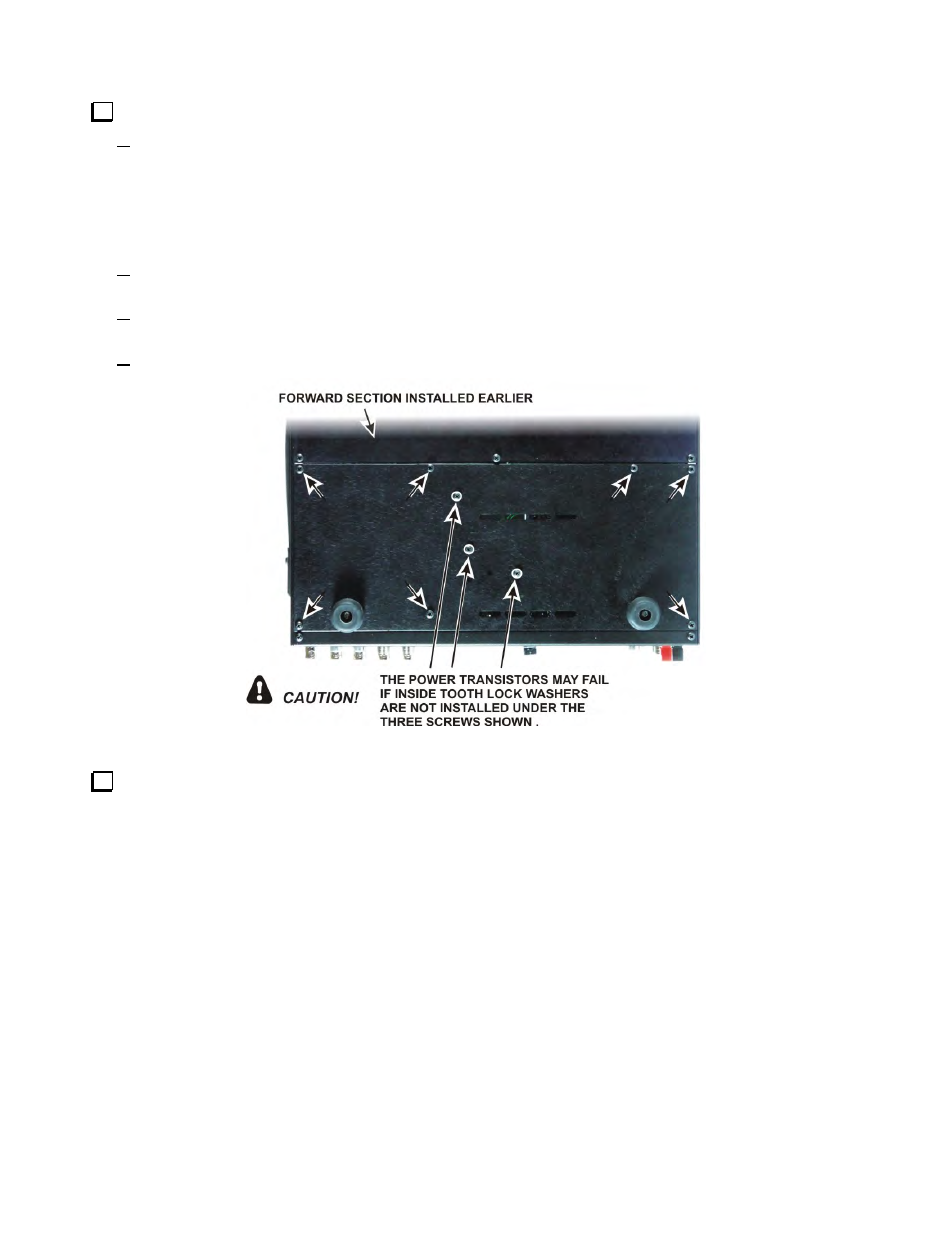
Figure 93. Checking Power Transistor Mounting Hardware.
Inspect the bottom cover screws to ensure you have inside tooth lock washers under the three screws shown
in Figure 93. Be sure all three screws are tight.