Caution – Elecraft K3 Assembly Manual User Manual
Page 51
50
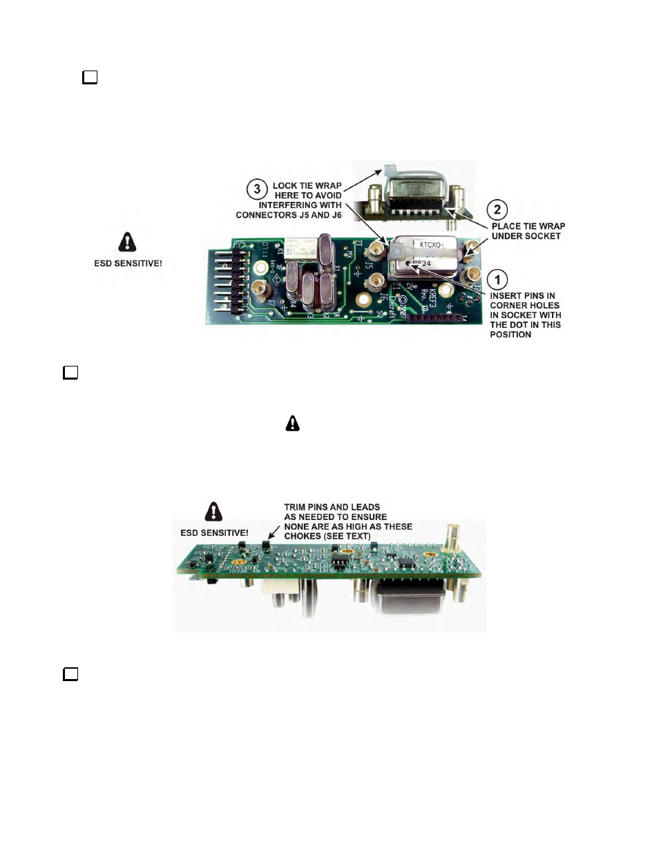
Mount the TCXO module on the KREF3 board as shown in Figure 69. Be certain the leads go into the
corner holes in the socket and the black dot is oriented toward connector J6 as shown. If you have a 1ppm
high-stability module, the dot may be light brown and not as close to the corner. If the module has only
three leads, the missing lead will be in the corner with the dot. If you have the standard 5ppm TCXO, the
bottom may be slightly above the socket when the leads are fully inserted. Tighten the tie wrap enough to
ensure the oscillator so it cannot fall out but do not bend the leads.
Figure 69. Mounting TCXO Module on KREF3 Board.
Inspect the bottom of the KREF3 to ensure no leads are higher than the chokes as shown below. The chokes
are the highest of the black surface-mount components on the board. Use your diagonal cutters to trim any
excessively long leads close to the board.
CAUTION
The objective is to be certain no bare leads touch the front panel shield when the board
is installed in the next step. Do not add spacers or insulating material between the board
and the front panel shield. It is important for proper shielding of the circuits that the
board sit very close to the front panel shield.
Figure 70. Checking Lead Lengths on KREF3 Board.
If you are installing the K3EXREF option, mount the K3EXREF board on the KREF3 board as shown in
the K3 K3EXREF Frequency Lock Option manual, Figures 8 and 9 (pages 9 and 10). Be sure to install the
shorting block as shown in Figure 8. After the KREF3 board is in place, be sure to connect the TMP connector
on the cable you installed earlier to the connector that passes through the front panel shield.