Caution – Elecraft K3 Assembly Manual User Manual
Page 39
38
CAUTION!
You may damage the encoders while installing the knobs in the next step unless you align
the flats in the knobs with the flats on the shafts as described below.
Press small knobs on the four controls under the left end of the LCD: SHIFT/LOW, HI/WIDTH,
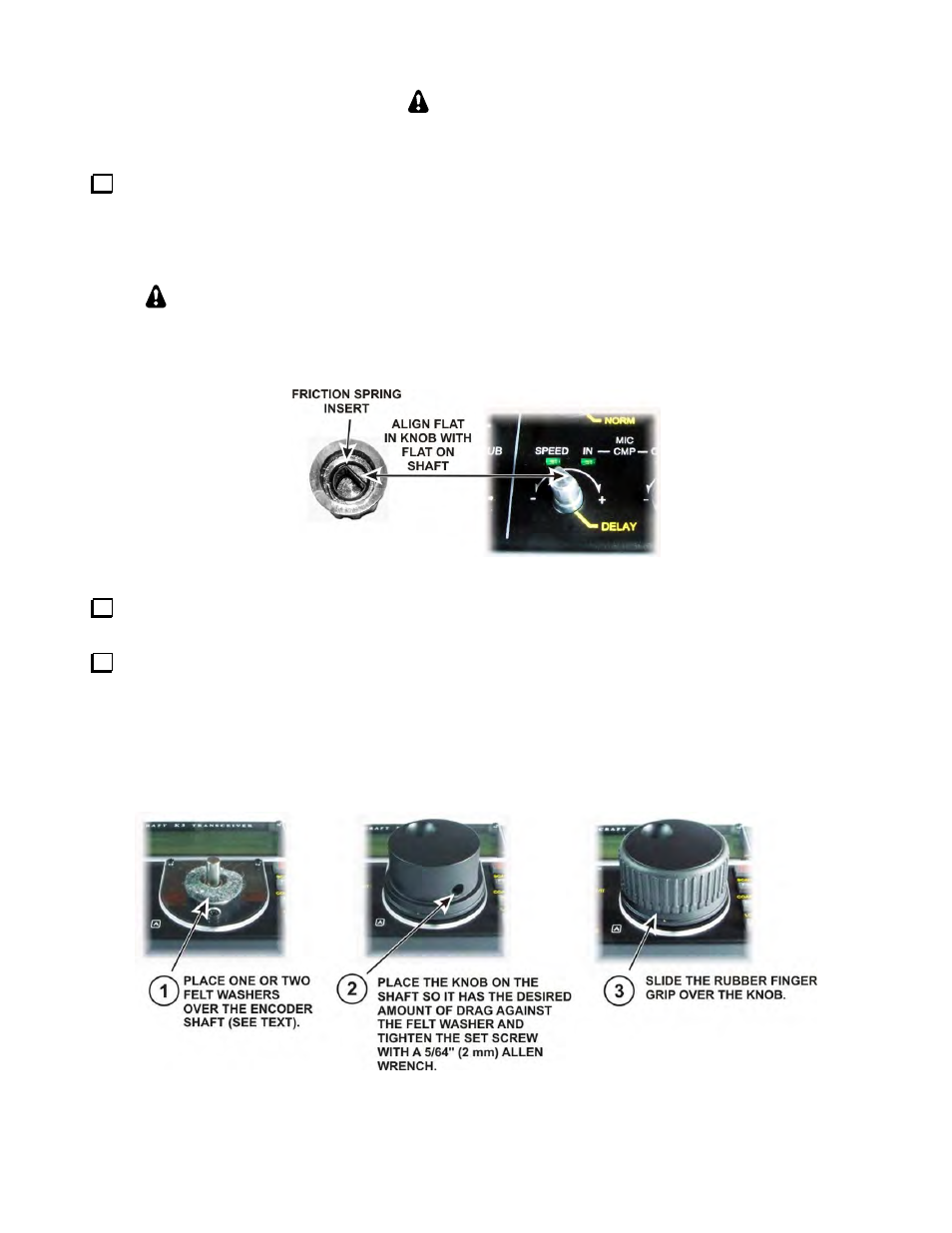
SPEED/MIC and CMP/PWR. These knobs are all the same size and are held in place by a friction spring as
shown in Figure 49. Align the flat in the knob with the flat on each shaft before pressing each knob in place. In
addition to the rotating encoder, each knob has a switch that is actuated by pressing the knob toward the panel.
You will feel the switch action when you press each knob onto the shaft.
If a knob feels very loose, check to see if the metal friction spring insert is in place as
shown below. If not it should be in the bag with the knobs. Slide the spring insert into the
knob and place it on the shaft. Friction will hold it and the knob securely once it is mounted.
Figure 49. Mounting Friction Knobs.
In the same manner, mount the slightly larger friction knob onto the RIT/XIT control in the lower right
corner of the front panel. The RIT/XIT control does not have the switch action of the other four encoders.
Mount the large knob on the VFO A encoder shaft below the LCD as shown in Figure 50. Adjust the
position of the knob against the felt washer to produce the desired amount of drag for smooth movement without
the knob turning too freely. Setting the panel face up and then placing the knob on the shaft so its weight
determines the pressure against the felt usually produces a satisfactory amount of friction. If you want to make
further adjustment and find it too sensitive, try a second felt washer under the knob. An extra felt washer is
included in the kit for this purpose. You can do this after assembly is completed. The finger grip slides off to
provide access to the set screw.
Figure 50. Mounting the VFO A Tuning Knob.