Elecraft K3 Assembly Manual User Manual
Page 61
60
Identify the bottom cover forward section by test fitting it on the bottom of the K3. The forward section is
the thinner panel with a notch along one edge (see Figure 84).
One side of the cover is fully painted. That is the outside. The other side has areas of bare metal left to
ensure good electrical contact with the other cabinet parts. Check the inside surface for any masking tape left
from the painting process. If found, peel it off.
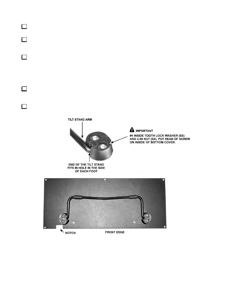
Attach the front feet and tilt stand to bottom cover section A as follows. Insert a 4-40 7/16” (11 mm) zinc
pan head screw (SS) through the cover with the screw head on the inside, and place a foot over the screw on the
outside (fully painted) of the cover. Orient the foot as shown in Figure 84. Place a #4 lock washer (SS) and 4-40
nut (SS) on the end of the screw inside the hole in the foot, and put your finger over the hole to hold the nut
against the screw. Turn the screw to start the nut onto the threads but do not tighten it. Repeat the procedure for
the second screw in the foot. Leave the foot as loose as possible without the hardware falling off.
Install the tilt stand and second foot as shown in Figure 84. You many need to press the foot against the tilt
stand to get the 4-40 7/16” (11mm) screws (SS) to pass through the cover and foot. Put a #4 lock washer (SS)
and nut (SS) on each screw as you did before.
Tighten all four screws. It should not be necessary to put a tool on the nuts. Friction against the feet and the
lock washers should hold them securely while you tighten them by turning the screw heads.
Figure 84. Installing Tilt Stand.