Elecraft K3 Assembly Manual User Manual
Page 66
65
Bottom Covers
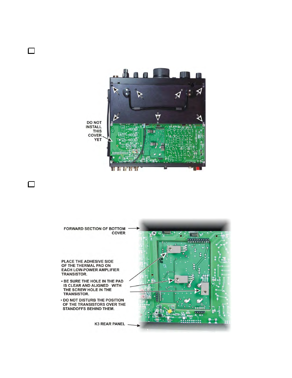
Turn the K3 over so the bottom is exposed. Position the forward section of the bottom cover with the feet
and bail toward the front as shown in Figure 91. Attach the cover with seven 3/16” (4.8 mm) black pan head
screws (SS) at the positions shown. Do not use washers.
Figure 91. Installing Bottom Cover Forward Section.
Locate the three thermal pads and clear the screw holes. They are already cut. If material is still covering
the holes, push a small tool through the hole to remove the unwanted material. Remove the protective backing
from each pad and press the adhesive side against a low-power amplifier transistor with the hole in the pad
aligned with the screw hole in the transistor as shown in Figure 92. Take care not to disturb the position of the
transistors over the standoffs.
Figure 92. Installing the Low Power Amplifier Transistor Thermal Pads.
- KX3 Owner's Manual (58 pages)
- KX3 Assembly Manual (47 pages)
- KX3 Assembly Manual Errata (5 pages)
- KX3-2M (30 pages)
- KX3-PCKT (2 pages)
- KX3 Mobile Installation And Operation Guide (17 pages)
- KX3 Guide for Blind Operators (7 pages)
- KX3 Quick Reference (2 pages)
- K3 Programmers Reference (26 pages)
- KX3 Speaker Grille Instructions (9 pages)
- KXFL3 Filter Option (12 pages)
- KXFL3 Filter Option Errata (2 pages)
- KXAT3 (5 pages)
- KXBC3 (13 pages)
- KXPD3 (4 pages)
- Proset Boom Headset (1 page)
- PX3 Owner's Manual (53 pages)
- PX3 Owners Manual Errata (2 pages)
- KXPA100 Manual (55 pages)
- KXPA100 Assembly Manual (27 pages)
- KXPA100 Assembly Errata (1 page)
- KXPA100 Programmers Reference (24 pages)
- KXAT100 Installation Manual (17 pages)
- KX1 Manual (96 pages)
- KXAT1 (12 pages)
- KXPD1 (7 pages)
- KXB30 (8 pages)
- KXB3080 (20 pages)
- K1 (91 pages)
- K1 1.09 F/W (1 page)
- KNB1 Manual (8 pages)
- KAT1 Manual (15 pages)
- KFL1-2 (2 pages)
- KTS1 (1 page)
- KBT1 Manual (8 pages)
- KBT1 Manual Errata (2 pages)
- K1BKLTKT LCD Mod Kit (6 pages)
- K2 Owner's Manual (171 pages)
- K2 Owner's Manual Errata (1 page)
- K2 PLL (4 pages)
- K2ATOBKIT (15 pages)
- K2ATOBKT (2 pages)
- K2 Keying Modification Instructions (4 pages)
- KPA100 Manual (74 pages)
- KPA100 Shield Upgrade (3 pages)