Elecraft K3 Assembly Manual User Manual
Page 48
47
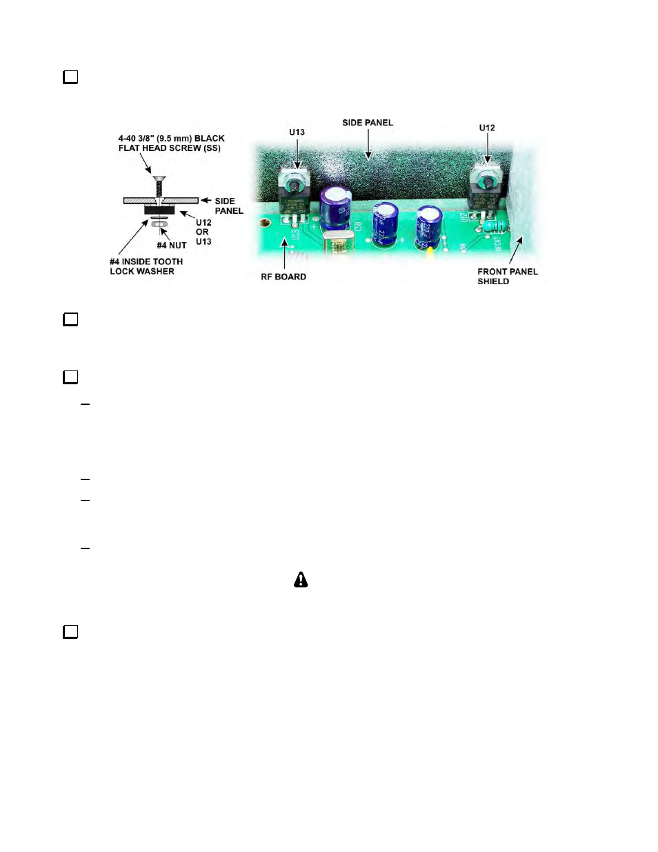
Attach voltage regulators U13 and U12 to the right side panel as shown in Figure 65 using a 4-40 3/8” (9.5
mm) black flat head screw (SS), #4 inside tooth lock washer and a #4 nut for each regulator as shown. When the
screws are tightened the tabs on U12 and U13 should lie flat against the side panel.
Figure 65. Attaching U12 and U13 to the Right Side Panel.
If you are installing the K3EXREF option, refer to the K3 K3EXREF Frequency Lock Option manual and
install the coaxial cable as shown in Figures 3, 4 and 5 on pages 7 and 8. Note that in your kit the K3’s bottom
cover and KREF3 board are not yet installed. They will be added later.
Replace the left side panel (with the handle) as follows:
Start the six 4-40 3/16” (4.8 mm) black flat head screws (SS) through the panel: three along the bottom,
one at the top rear, one at the top front, and one just below the front end of the handle. It is normal to
adjust the position of the panels slightly when assembling so the screw holes line up. The cabinet will
become structurally sound and rigid with all the panels, including the top and bottom covers, are
mounted.
Start one 4-40 3/16” (4.8 mm) black flat head screw (SS) at the top corner of the front panel assembly.
Inspect the area where the side panel meets the front panel shield, and make sure there is positive
mechanical contact at the screw just below the end of the handle and about 3/4” (19 mm) above the RF
board. The area of the side panel around that point is clean metal.
Tighten all seven screws. Be sure all the screws are tight, including the screw near the forward end of
the handle that threads into the front panel shield.
CAUTION
Failure to establish a solid contact at that point may result in birdies in the receiver.
Fasten the top center of the front panel assembly to the front panel shield with a 4-40 3/16” (4.8 mm) black
flat head screw (SS).