Caution, Kref3 reference oscillator – Elecraft K3 Assembly Manual User Manual
Page 50
49
Initial Power On Check
The following check confirms that the power supply and power control circuits are working properly. Be sure
your K3 passes the resistance tests above before proceeding.
CAUTION!
If you see or smell smoke when applying power, turn the K3 off and remove the power
cable immediately, then locate the source.
Connect your 13.8 VDC power supply to the 12VDC IN connector on the rear panel. If you do not have a
suitable cable handy, assemble the Power Supply Cable Kit supplied with your K3. Do not connect a key,
microphone or other accessories to the K3 at this time.
Tap (press for less than 1/2 second) the front panel
P O W E R
button and confirm the LCD display lights.
There may be a delay of about 1 second before the display lights. Some front panel LEDs may light as well, and
you may notice D33 on the RF board, next to the crystal filters, light. Ignore any error messages on the display
and do not try to operate the radio at this time. You’ll get to do that soon.
Tap the front panel
P O W E R
button again to turn the K3 off and disconnect your external power supply.
KREF3 Reference Oscillator
KREF3 Description
The KREF3 module’s 49.380-MHz temperature-compensated crystal oscillator (TCXO) is the common
reference for the K3’s synthesizers. See Theory of Operation, KREF3, in the K3 Owner’s Manual for more
information.
KREF3 Installation Procedure
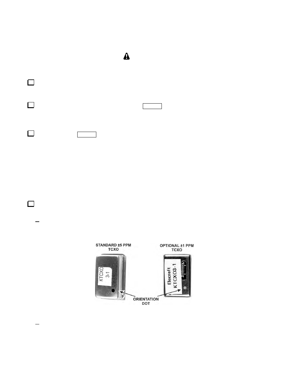
Locate the Temperature-Compensated Crystal Oscillator (TCXO) module. If you ordered the optional
±1 ppm TCXO it will be supplied instead of the standard 5 ppm module (see Figure 68).
Note the position of a small colored dot on the top of the module. It is sometimes faint and may be hard
to see without good light. The dot allows you to orient the module correctly in the socket. Some
modules have four pins while others have only three. If your module has three pins, the missing pin is in
the same corner as the painted dot.
Figure 68. TCXO Modules.
If you have the optional ±1 ppm module, it is supplied with a thin flat insulator that fits over the pins to
cover the bottom. Place the insulator over the pins. This insulator is not used on the standard ±5 ppm
module.