Elecraft K3 Assembly Manual User Manual
Page 47
46
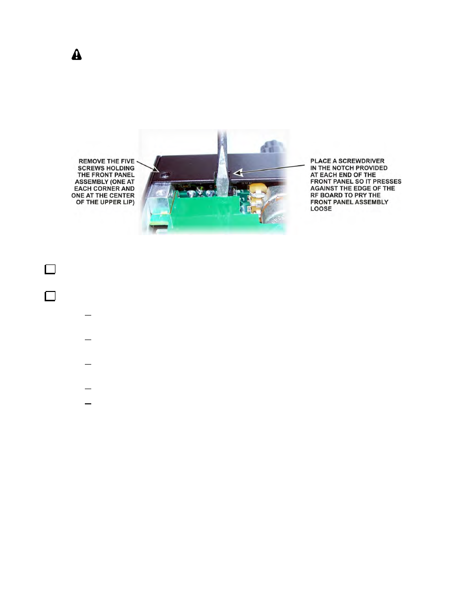
REMOVING THE FRONT PANEL: If you need to remove the front panel assembly,
remove the five screws holding it to the chassis (three on the top lip and two on the bottom),
turn the unit upside down and use a screwdriver in the two pry slots provided as shown in
Figure 64. Do not insert the screwdriver deep enough to strike components on the boards!
Pry each end in short increments until the connectors separate. Either a blade (as shown) or
Phillips screwdriver may be used. Note that you may need to remove the left side panel and
the 2D mounting screw shown in Figure 63.
Figure 64. Removing the Front Panel.
Secure the front panel assembly at the bottom lip to the 2D fasteners at the forward edge of the RF board
with two 4-40 3/16” (4.8 mm) black pan head screws (SS).
Replace the right side panel (the panel with the feet) as follows:
Start four 4-40 3/16” (4.8 mm) black flat head screws (SS) through the side panel: three along
the bottom and one at the front top. Make the threads have engaged, but do not tighten them yet.
Start one 4-40 3/16” (4.8 mm) black flat head screw (SS) through the rear panel into the 2D
fastener shown in Figure 61.
Start one 4-40 3/16” (4.8 mm) black flat head screw (SS) at the top right corner of the front
panel assembly, nearest the side panel.
Tighten all six screws
Replace the 4-40 1/4” (6.4mm) zinc pan head screw holding the KANT3 (or KAT3) board
shown in Figure 61.