Elecraft K3 Assembly Manual User Manual
Page 46
45
ESD SENSITIVE: Wear a grounded wrist strap or touch an unpainted metal ground
before handling the RF Board in the following steps.
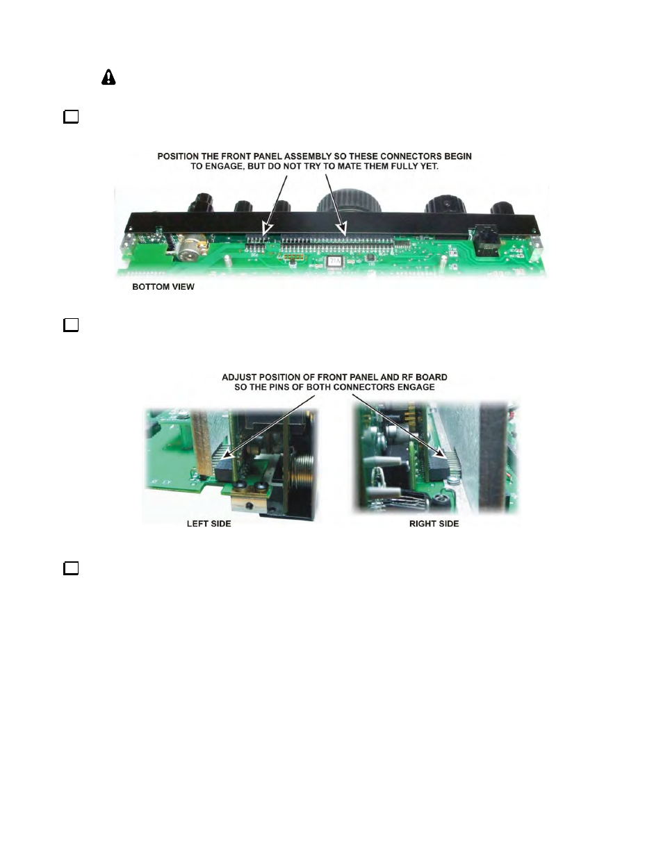
Turn the chassis upside down and position the front panel so the pins of P30 and P35 on the bottom of the
RF board just begin to engage the connectors on the lower edge of the front panel assembly. Do not fully mate
them yet.
Figure 62. Mounting Front Panel Assembly - Connectors P30 and P35.
Look at the two multi-pin connectors on the top of the RF board to see if they are engaging the
corresponding connectors on the front panel assembly (see Figure 63). Adjust the position of the RF board or the
front panel assembly to ensure they are mating properly.
Figure 63. Mounting Front Panel Assembly - Connectors P50 and P51.
With the pins of all four connectors started, press the front panel onto the RF board connectors. Press only
from the bottom of the front panel to avoid flexing the RF board. You can use your fingers to press on the back
side of each multi-pin connector on the top of the RF board while holding the front panel to engage them. There
may be small areas of pins showing even after they are mated. You will know they are properly mated when the
screw holes on the bottom lip of the front panel assembly line up with the screw holes in the 2D fasteners on the
bottom of the RF board.