Elecraft K3 Assembly Manual User Manual
Page 35
34
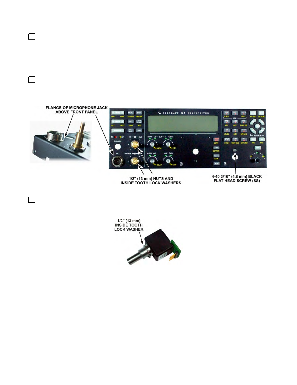
Ensure the flange on the MIC connector is not caught behind the panel. The flange should be slightly above
the panel as shown all the way around its circumference as shown in Figure 41. It may be a snug fit requiring
you to press it into place, pushing on the back of the connector. If the connector refuses to fit through the hole in
the front panel, use a sharp tool to carefully remove the paint from the inside edge where the connector is
binding against the hole. Work from the inside of the front panel to avoid damaging the paint on the front edge
of the MIC connector hole.
Secure the front panel to the board with a 4-40 3/16” (4.8 mm) black flat head screw (SS) above the control
opening near the right end and a 1/2” (13mm) nut and inside tooth lock washer on each concentric pot bushing
near the left end as shown. Tighten the screw and nuts only until you feel firm resistance. Be very careful not to
scratch the front panel.
Figure 41. Mounting the Front Panel on the Front Panel Board.
Two identical encoder assemblies are provided for VFO A and VFO B. Select one encoder and place a 1/2”
(13mm) inside tooth lock washer over the threaded shaft as shown in Figure 42. This will be the VFO A
encoder.
Figure 42. VFO A Encoder Assembly Preparation for Installation.