Elecraft K3 Assembly Manual User Manual
Page 25
24
At the upper rear corner of the side panel you just identified in the previous step, mount a 2D fastener as
shown in Figure 22, using a black 4-40 1/2” (13 mm) flat head screw (SS). Remember that flat head screws are
measured from the flat top to the end of the threads. Note that the screw extends some distance through the 2D
fastener.
Figure 22. Mounting 2D fastener for KANT3 or KAT3 Standoff.
Screw a 4-40 1/2” (13 mm) standoff onto the exposed end of the screw as shown in Figure 23. Do not use a
lock washer between the standoff and the 2D fastener. Tighten the standoff securely against the 2D fastener.
Set the side panel aside temporarily.
Figure 23. KANT3/KAT3 Mounting Standoff.
Mounting the KANT3 or KAT3, Side and Rear Panels
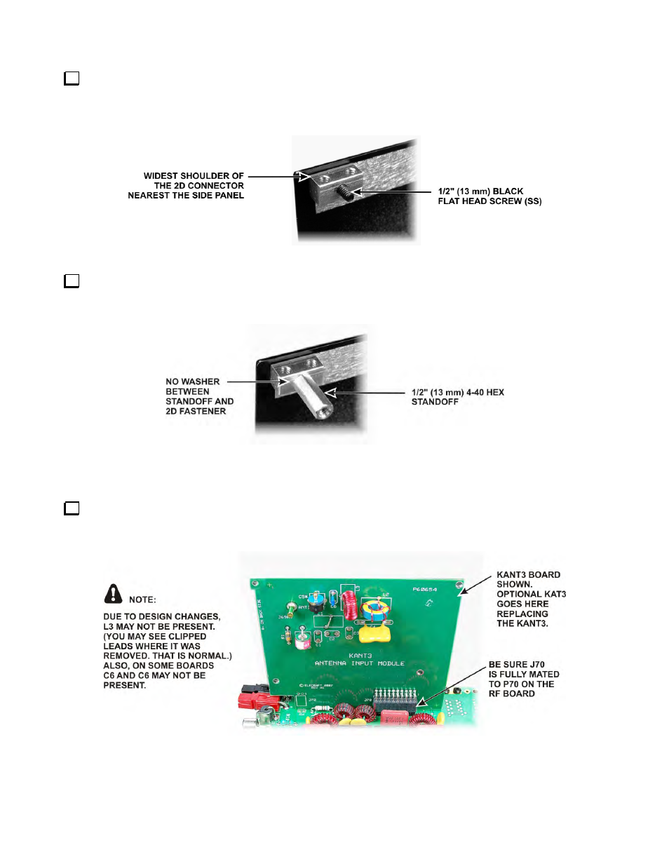
Insert J70 on the KANT3 or the KAT3 board into P70 near the red and black APP power connectors at the
right rear corner of the RF board. The KANT3 board is shown in Figure 24. The KAT3 board fits exactly the
same way with the toroidal inductors toward the center of the RF board. I
Figure 24. Installing the KANT3 or KAT3 Board.