Elecraft K3 Assembly Manual User Manual
Page 34
33
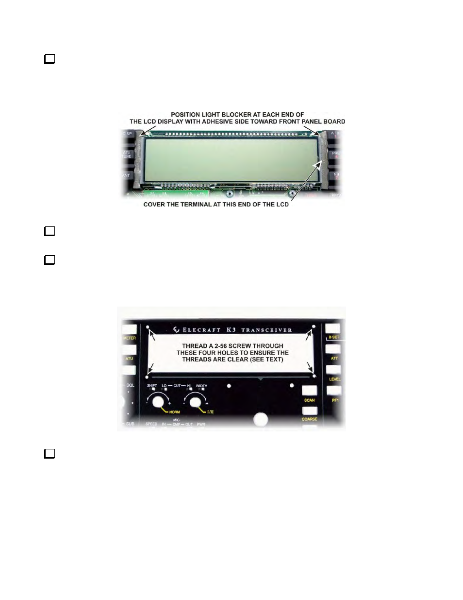
Install the two soft foam light blockers at the ends of the LCD display as shown in Figure 39. Remove the
paper strip covering the adhesive on each blocker and stick that side against the board (or the lip at the base of
the switch buttons) so it stands up between the switches and the LCD. Push them down so the adhesive side is
against the board or base of the switches and that they cover ends of the LCD, including the terminals at the
right hand end of the LCD as shown.
Figure 39. Installing LCD Light Blocker.
Locate the front panel and inspect the inside surface for any masking tape covering the holes left during the
painting process. If any is found peel it off.
Locate a 2-56 5/32” (4.0 mm) black pan head screw found in the small envelope marked E850340 LCD
Bezel Screws Envelope 2-56 5/32 Blk Ox PH+(700149). Thread the screw through each of the four threaded
holes at the corners of the opening in the front panel for the LCD to ensure they are clear of paint (see Figure
40). Lubricate the screw if the fit is tight. A drop of water on the threads will usually work well and it is easier to
wipe away excess water than oil. Return the screw to the envelope until it is called for later.
Figure 40. Checking 2-56 Threaded Screw Holes.
Place the front panel board face up on your work surface, then set the front panel over it as shown in
Figure 41. Check to ensure the LEDs above the four controls under the LCD display, the red and yellow LEDs
below the POWER button, and the three LEDs above the control in the lower right corner of the panel are
positioned in their openings. If necessary, lift the panel off and gently adjust the position of the LEDs.