Elecraft K3 Assembly Manual User Manual
Page 26
25
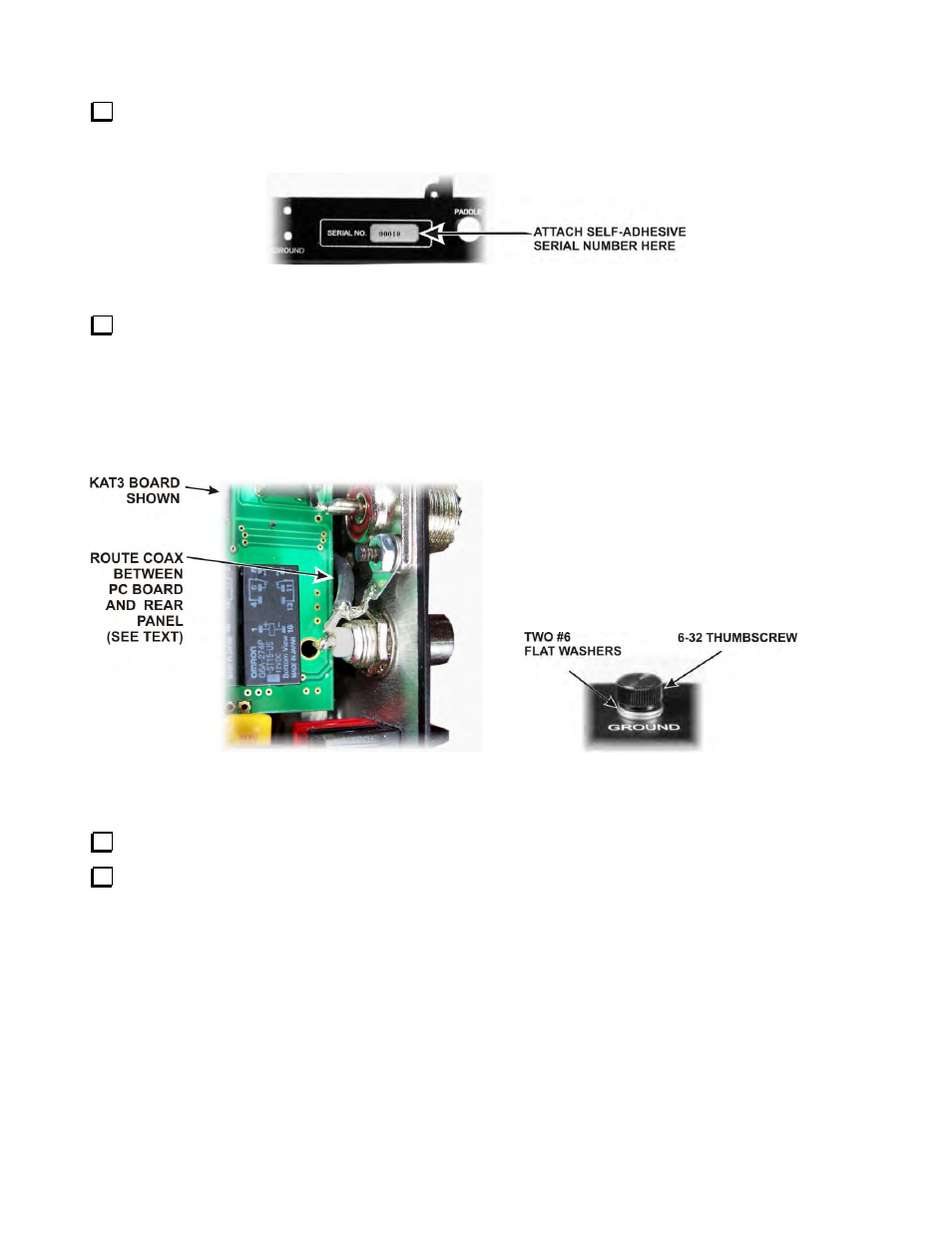
Peel the backing from the self-adhesive serial number label and attach it to the back panel as shown in
Figure 25. You may wait until the assembly is finished before attaching the serial number, but at this point you
can lay the panel flat on the work surface to easily position the label square within the outline.
Figure 25. Attaching Serial Number.
Position the rear panel on the K3 chassis assembly so that the SO239 connector(s) are at the end nearest the
KANT3 or KAT3 board. If installed, the coax cable attached to the AUX RF connector should pass between the
rear panel and the KAT3 or KANT3 board (see Figure 26). Thread the 6-32 thumbscrew into the ground
terminal position near the center of the rear panel as shown in Figure 27. Use two #6 flat washers between the
thumbscrew and the back panel as shown. If the hole in the rear panel does not line up with the threaded hole in
the ground bracket mounted on the RF board, loosen the side panel screws at the end nearest the rear panel so
you can adjust the position of the rear panel as needed.
Figure 26. Routing AUX RF Connector Coax.
Figure 27. Installing Rear Panel Ground Screw
If you loosened the side panel screws in the previous step, tighten them again now.
Attach the bottom lip of the rear panel to the 2D fasteners at the rear corners of the RF board with 4-40,
3/16” (4.8 mm) black pan head screws (SS). (Note that all the screws used on the bottom of the K3 are black
pan head screws.)