Elecraft K3 Assembly Manual User Manual
Page 44
43
Squeeze the boards together while ensuring the pins are mating with the connectors until the DSP board is
resting against the three standoffs on the back of the front panel board that you installed earlier. The two
connectors will not mate completely. About 1/4” (6.4mm) of the pins may be visible when the DSP board is
positioned against the standoffs. There are other connectors on the DSP board as well, but the two that mate
with J31 and J32 are the only ones that connect between the front panel and DSP boards.
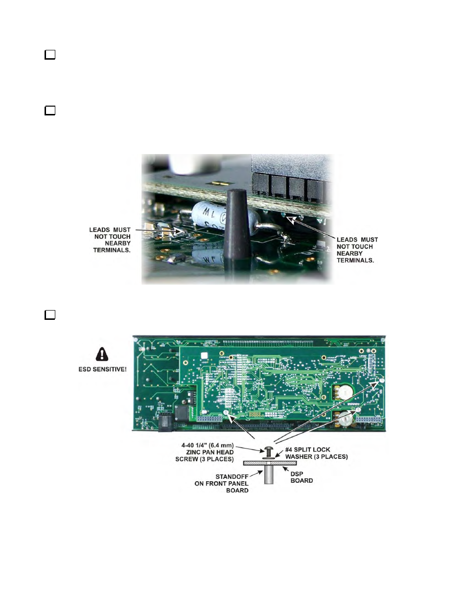
If you installed the Auxiliary DSP board for the KRX3 and adjusted the position of resistor R3 as shown in
Figure 55, look between the DSP boards and the front panel board to verify that the leads are not touching any
terminals on either the aux DSP or front panel boards (see Figure 58). If necessary, unplug the DSP board
assembly and adjust the position of R3 to ensure the leads are clear of other solder pads before proceeding.
Figure 58. Checking the Position of R3.
Secure the DSP board to the front panel board with three 4-40 1/4” (6.2 mm) zinc pan head screws and split
lock washers as shown in Figure 59.
Figure 59. Mounting the DSP Board.