Elecraft K3 Assembly Manual User Manual
Page 49
48
Resistance Checks
The following resistance checks confirm that the main power busses in the K3 aren’t shorted to ground. If any of
the values measured are lower than specified, inspect the unit carefully for loose hardware that is caught
between components on the boards or for improperly mated connectors.
Use your digital multimeter (DMM) to measure the resistance across the red and black 12VDC IN
connectors on the rear panel. The resistance should be greater than 3K ohms. It may be much higher, depending
upon which way you connect the leads. Your DMM may indicate the value is so high it is out of the range of the
instrument and as it does when in ohms mode and the probes are not touching anything. If you are not sure, refer
to your DMM instruction manual to interpret the reading.
Use your DMM to measure the resistance between the end of R36 and ground at the exposed copper around
the screws for the 2D fastener (see Figure 66). The resistance must be greater than 150 ohms.
Figure 66. R36 Test Point.
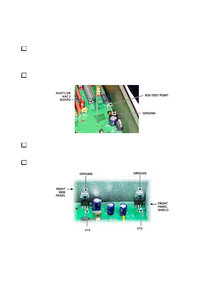
Use your DMM to measure the resistance between the terminal on U12 and ground shown in Figure 67 .
The resistance must be greater than 500 ohms (although in some K3’s it may be only slightly greater than 500
ohms).
Use your DMM to measure the resistance between the terminal on U13 and ground shown in Figure 67.
The resistance must be greater than 125 ohms.
Figure 67. U12 and U13 Test Points.