Caution – Elecraft K3 Assembly Manual User Manual
Page 37
36
CAUTION!
In the following steps you will attach the plastic LCD cover and VFO A trim panels to the
front cover using small screws. Use the screws specified in each step. Do not over-tighten
these screws. Tighten the screws only to the point where you feel some resistance. It is very
easy to strip the threads, especially the screws holding the LCD cover. If you strip these
threads the only remedy is to obtain a new front panel!
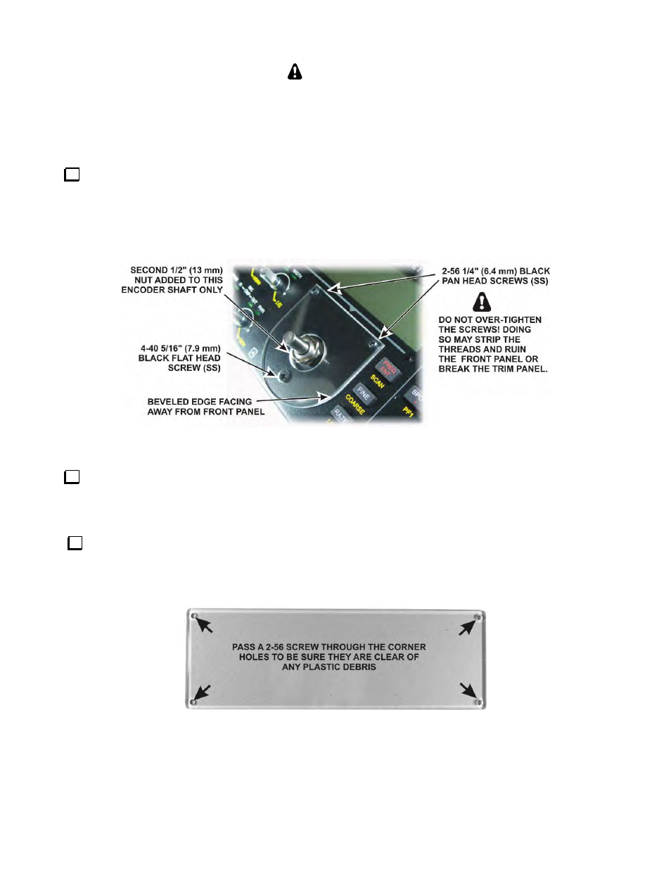
Brush or blow any dust or lint away from the front panel area around the encoder shaft under the LCD, then
mount the trim panel as shown in Figure 45, oriented so the beveled edges are away from the front panel. Use
the 2-56 1/4” screws and the 4-40 5/16” screw found in the small envelope marked E850241 VFO A Bezel
Screws Envelope. Tighten the screws only until they come into firm contact with the trim panel. (If you had
already opened the envelope, be sure you are using the 1/4” (6.4 mm) screws and not the shorter 5/32” (4.0 mm)
screws.) Be careful not to over-tighten the screws or you may strip the threads or break the trim panel!
Figure 45. Mounting VFO A Trim Panel.
Locate the clear plastic LCD cover and four 2-56 5/32” (4.0 mm) black pan head screws. These screws are
in the small envelope marked E850340 LCD Bezel Screws Envelope 2-56 5/32 Blk Ox PH+(700149) or (SS).
Be sure you are using 5/32” (4.0 mm) screws to install the cover in the following steps. Longer screws may
extend through the front panel and break the glass front of the LCD!
Check the LCD cover screw holes by sliding a 2/56 screw through them to be sure they are clear of any bits
of plastic that might interfere with the screws. The screws should side easily through the holes. Pushing them
back and forth through the holes should loosen the fit if they are tight. When finished, ensure the LCD cover is
free of dust, smudges and fingerprints.
Figure 46. Checking LCD Cover Screw Holes.