Elecraft K3 Assembly Manual User Manual
Page 40
39
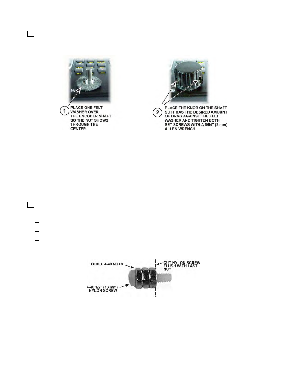
Mount the last knob on the VFO B encoder shaft to the right (under the pushbutton switches) as shown in
Figure 51. Before tightening both set screws, adjust the position of the knob against the felt washer to produce
the desired amount of drag for smooth movement without the knob turning too freely.
Figure 51. Mounting the VFO B Knob.
Mounting the Subreceiver Auxiliary DSP Board
If you purchased the optional KRX3 Subreceiver with your K3, install the KXR3 auxiliary DSP board as
follows. If you did not purchase the KRX3, go to Installing the KDVR3 Digital Voice Recorder Option on page
41 if you purchased the KDVR3 Digital Voice Recorder Option with your K3. If you do not have the KDVR3,
go directly to Mounting the DSP Board Assembly on the Front Panel on page 42.
The parts called for in the following procedure are included in the KRX3 Subreceiver kit. Install only the
Auxiliary DSP board as described in the following steps. You will complete the KRX3 installation after the
basic K3 is assembled, calibrated and tested.
If your KRX3 kit was supplied with 1/4” (6.4mm) long nylon screws, skip this step. If you have 1/2”
(13mm) nylon screws, cut all three of them to length as follows:
Screw three 4-40 nuts onto the 1/2” (13 mm) 4-40 nylon screw as shown in Figure 52.
Cut off the nylon screw flush with the last nut. Sharp diagonal cutters or a knife will cut the nylon.
After cutting, remove all three nuts. (The nuts establish the correct length for the screw and “clean up”
the thread where you cut the screw.)
Figure 52. Preparing the Nylon Screw.