Elecraft K3 Assembly Manual User Manual
Page 29
28
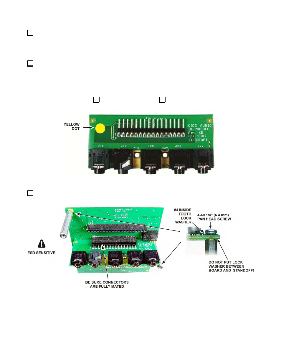
Mount two 1-1/4” (31.8 mm) standoffs in the two holes on the KIO3 board as shown in Figure 33 using a
zinc 4-40 1/4” (6.4 mm) screw and inside tooth lock washer at each standoff. One is in the corner and the other
is about half way down the opposite side of the board. Do not put lock washers between the standoffs and the
board.
Inspect the KIO3 Audio board for a yellow dot at one corner of the board (see below). There are two
versions of the audio board, one with a yellow dot and one without. Both versions provide the same performance
but the version with a yellow dot requires a simple change to the firmware setup when you apply power to test
your K3. Check either “yellow dot” or “no yellow dot” below to remind you which version board you are
installing.
Yellow Dot
No Yellow Dot
Figure 32. Yellow Dot on KIO3 Audio Board.
Plug the Audio I/O daughter board into J91 as shown in Figure 33. The second daughter board will be
installed later.
Figure 33. Preparing the KIO3 Board for Installation.
- KX3 Owner's Manual (58 pages)
- KX3 Assembly Manual (47 pages)
- KX3 Assembly Manual Errata (5 pages)
- KX3-2M (30 pages)
- KX3-PCKT (2 pages)
- KX3 Mobile Installation And Operation Guide (17 pages)
- KX3 Guide for Blind Operators (7 pages)
- KX3 Quick Reference (2 pages)
- K3 Programmers Reference (26 pages)
- KX3 Speaker Grille Instructions (9 pages)
- KXFL3 Filter Option (12 pages)
- KXFL3 Filter Option Errata (2 pages)
- KXAT3 (5 pages)
- KXBC3 (13 pages)
- KXPD3 (4 pages)
- Proset Boom Headset (1 page)
- PX3 Owner's Manual (53 pages)
- PX3 Owners Manual Errata (2 pages)
- KXPA100 Manual (55 pages)
- KXPA100 Assembly Manual (27 pages)
- KXPA100 Assembly Errata (1 page)
- KXPA100 Programmers Reference (24 pages)
- KXAT100 Installation Manual (17 pages)
- KX1 Manual (96 pages)
- KXAT1 (12 pages)
- KXPD1 (7 pages)
- KXB30 (8 pages)
- KXB3080 (20 pages)
- K1 (91 pages)
- K1 1.09 F/W (1 page)
- KNB1 Manual (8 pages)
- KAT1 Manual (15 pages)
- KFL1-2 (2 pages)
- KTS1 (1 page)
- KBT1 Manual (8 pages)
- KBT1 Manual Errata (2 pages)
- K1BKLTKT LCD Mod Kit (6 pages)
- K2 Owner's Manual (171 pages)
- K2 Owner's Manual Errata (1 page)
- K2 PLL (4 pages)
- K2ATOBKIT (15 pages)
- K2ATOBKT (2 pages)
- K2 Keying Modification Instructions (4 pages)
- KPA100 Manual (74 pages)
- KPA100 Shield Upgrade (3 pages)