Elecraft K3 Assembly Manual User Manual
Page 27
26
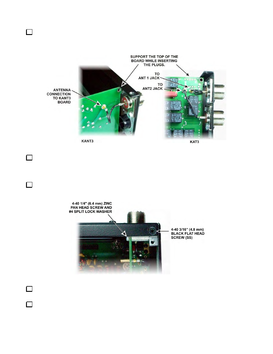
Connect the wires from the SO239 connector(s) to the KANT3 or KAT3 board as shown in Figure 28. Use
needle-nose pliers to grip the terminals on the wire ends and carefully insert the connectors straight into the
holes in the board. They may be very difficult to insert unless they are perfectly aligned. While inserting the
plugs, support the board with your fingers to avoid putting stress on the connector at the bottom.
Figure 28. ANT Connections to KANT3 or KAT3 Boards.
Attach the right side panel to the RF board assembly four 4-40 3/16” (4.8mm) black flat head screws: three
along the bottom and one at the top front into the 2D fastener on the front panel shield. Do not use washers.
Note that there are two open holes for screws to secure voltage regulators U12 and U13. They will be installed
later.
Mount the KANT3 or KAT3 board to the standoff on the side panel with a 4-40 1/4” (6.4mm) zinc pan
head screw and a #4 split lock washer under the screw head as shown in Figure 29. Do not place a washer
between the board and the standoff.
Figure 29. Installing KANT3/KAT3 Mounting Screw.
Install a 4-40 3/16” (4.8 mm) black flat head screw (SS) to secure the top of the rear panel to the 2D
fastener as shown in Figure 29
Install another 4-40 3/16” (4.8 mm) black flat head screw (SS) at the opposite end of the rear panel to
secure it to the top 2D fastener on the left side panel. When properly positioned, the rear panel should fit snugly
against the inside edge of the side panel as shown in Figure 29. Verify the fit is correct at both ends. If necessary
loosen the 2D fastener screws enough to adjust the position of the panels. .